Page 1
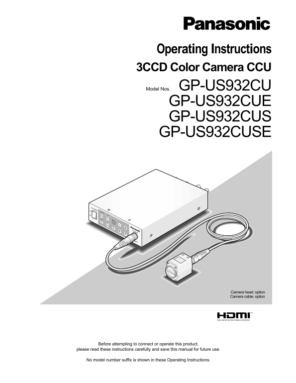
Operating Instructions 3CCD Color Camera CCU Model Nos. GP-US932CU GP-US932CUE GP-US932CUS GP-US932CUSE DC POWER OFF LOWSCENE BAR FREEZEMENU AWC EXPAND D RANGE SEL GP-US932 CAMERA Camera head: option ...
Page 2
We declare under our sole responsibility that the product to which this Wij verklaren als enige aansprakelijke, dat het product waarop deze declaration relates is in conformity with the standards or o...
Page 3
Important Safety Instructions 1) Read these instructions. 2) Keep these instructions. 3) Heed all warnings. 4) Follow all instructions. 5) Do not use this apparatus near water. 6) Clean only with dry ...
Page 4
CONTENTS Important Safety Instructions ............................................................................................................3 Limitation of Liability ..............................
Page 5
Limitation of Liability THIS PUBLICATION IS PROVIDED "AS IS" WITHOUT WAR- THIS PUBLICATION COULD INCLUDE TECHNICAL INAC- RANTY OF ANY KIND, EITHER EXPRESS OR IMPLIED, CURACIES OR TYPOGRAPHIC...
Page 6
Precautions Do not attempt to disassemble this product. Clean the faceplate with care. To prevent electric shock, do not remove screws or covers. Do not clean the faceplate with strong or abrasive det...
Page 7
Be sure to remove this product if it is not in use. Radio interference When the product is used near TV/radio antenna, strong electric field or magnetic field (near a motor or a trans- former), images...
Page 8
Preface This system is a compact and light type HD camera control unit (hereafter called CCU) with high image quality and multiple functions by introducing digital signal processing. The camera head i...
Page 9
Major Operating Controls and Their Functions ■Camera head Important: Be sure to turn off the power of the CCU before con- Lens mount section necting or disconnecting the camera cable. C-mount lens is ...
Page 10
Notes: Important: Pressing a button other than the [g] and [h] but- When the camera head is not connected, pressing tons provides freeze cancellation. the [BAR/AWC] button does not activate any opera-...
Page 11
<Rear> ● GP-US932CU, GP-US932CUE TV ON OR CS NR ● GP-US932CUS, GP-US932CUSE CS TV ON OR CS NR !3 HDMI output connector [HDMI] (* only for GP- output connector, SDI output connector, and HDMI out...
Page 12
!8 12 V DC power connector [DC 12V IN] @2 SDI output connector [SDI] This connector is used to connect an external DC (* only for GP-US932CUS, GP-US932CUSE) power supply of 12 volts (2 A or more). Thi...
Page 13
Installation/Connection Caution: ONLY CONNECT THIS TO 12 V DC CLASS 2 POWER SUPPLY. Be sure to connect the grounding lead to the GND terminal. The following shows how to mount the camera on the tripod...
Page 14
■How to mount lens Important: Be sure to turn off the power of the CCU before mounting a lens. A lens whose projection length of the lens mount section is 4 mm or less shall be used. The recommended l...
Page 15
Setting Procedures Performing each setting item on the SETUP menu should be completed in advance to use this unit. Perform the settings for each item in accordance with the conditions of the camera sh...
Page 16
■Basic operations To return to the camera image screen after storing the settings, move the cursor to "END" and press the [SEL] The description below explains how to operate the SETUP button...
Page 17
1. Camera title setting [CAMERA ID] <Character entry> To revise the character, move the cursor to "←" or "→" This item specifies the camera title. The camera title that and p...
Page 18
2. ELC setting [ELC] MANU: The detection area can be manually specified. (☞ page 18) Setting ELC (electronic light control) to ON provides auto- AUTO: The dark areas are automatically covered and mati...
Page 19
3. Electronic shutter setting [SHUTTER] Important: The "LOW" level cannot be larger than the "HIGH" level. The electronic shutter speed is specified. The speed is When "SENS U...
Page 20
7. Scene file setting [SCENE FILE] Move the cursor to "DTL MODE" on the "SCENE FILE" screen and press the [SEL] button. Registration of details, gamma, hue, etc. as a scene file in...
Page 21
Important: [WHITE CLIP] Adjusts the white clip level. In the case of the following, "---" appears and gamma Be sure to view a waveform monitor or a color video monitor adjustment is not avai...
Page 22
USER (default),B-Mg, Mg, Mg-R, R, R-Ye, Ye, Ye-G, G, Note: G-Cy, Cy, Cy-B, and B Every time the [SEL] button is pressed, the size of the rectangle cursor changes in the order of large → medi- Press th...
Page 23
8. White balance setting [WHITE BAL] 9. Black balance setting [BLACK BAL] The white balance adjustment is selectable from the follow- The black balance adjustment is generally unnecessary, ing. but th...
Page 24
10. Synchronization setting [SYNC] 11. Electronic zoom setting [ELECTRIC ZOOM] The synchronization state is displayed. The horizontal phase in the external synchronization can also be adjusted. Select...
Page 25
SEL Menu The SEL menu is a simplified menu that can be called up ■Button assignment by pressing the [SEL] button while an image is displayed. Only pressing the [e] or [f] button allows users to assign...
Page 26
Troubleshooting Before asking for repairs, check the symptoms with the following table. Contact your dealer if a problem cannot be solved even after checking and trying the solution in the table or a ...
Page 27
Reference Symptom Cause/solution pages Is the lens aperture appropriately adjusted? Check whether the aperture is appropriately adjusted. Blurred screen Use lenses with recommended F number or higher ...
Page 28
Specifications ●GP-US932CU/GP-US932CUS Power source: 12 V DC Power consumption: 15 W (excluding camera head) Pick-up system: Micro prism system Image sensor: 1/3" 3CCD, interline transfer (IT) eq...
Page 29
●GP-US932CUE/GP-US932CUSE Power source: 12 V DC Power consumption: 15 W (excluding camera head) Pick-up system: Micro prism system Image sensor: 1/3" 3CCD, interline transfer (IT) equipped (progr...
Page 30
Standard Accessories ●GP-US932CU/GP-US932CUS Operating Instructions (This document) .............................................................. 1 pc. Warranty Card for U.S. Field .....................
Page 32
Information on Disposal for Users of Waste Electrical & Electronic Equipment (private households) This symbol on the products and/or accompanying documents means that used electrical and electroni...