FAGOR BZY97C10 GP Data Sheet - FAGOR BZY97C200 GP
Summary
This comprehensive guide provides detailed technical specifications and performance data for our robust series of Zener Diodes. Designed for critical voltage regulation applications, these components offer reliable stabilization across a wide range of voltages, from 10V to 350V. The manual covers essential electrical characteristics, mounting guidelines, and detailed characteristic curves (including thermal resistances) necessary for both PCB designers and electronics engineers ensuring accurate circuit integration. Ideal for professionals sourcing high-reliability power management solutions.
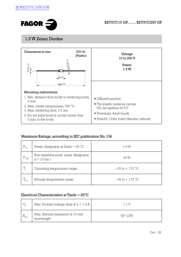
Page 1 Text Content
查询BZY97C10供应商
BZY97C10 GP........ BZY97C200 GP
1.5 W Zener Diodes
Dimensions in mm. DO-41
Voltage
(Plastic)
10 to 200 V
Power 1.5 W
Mounting instructions 1. Min. distance from body to soldering point,
• Diffused junction
4 mm.
• The plastic material carries
2. Max. solder temperature, 350 °C.
U/L recognition 94 V-0
3. Max. soldering time, 3.5 sec.
• Terminals: Axial Leads
4. Do not bend lead at a point closer than
2 mm. to the body. • Polarity: Color band denotes cathode
Maximum Ratings, according to IEC publication No. 134
Ptot Power dissipation at Tamb = 60 o C 1.5 W
Non repetitive peak zener dissipation PZSM 40 W (t = 10 ms.)
Tj Operating temperature range – 55 to + 175 °C
Tstg Storage temperature range – 55 to + 175 °C
Electrical Characteristics at Tamb = 25°C
VF Max. forward voltage drop at IF = 1.0 A 1.1 V
Max. thermal resistance at 10 mm. Rthj-a 50° C/W lead length
Oct - 02
Page Summary Contents For FAGOR BZY97C10 GP Data Sheet - FAGOR BZY97C200 GP
Manual Details
| Brand | Fagor |
|---|---|
| Pages | 5 |
| File Size | 74.24 KB |
| Published | May 19, 2026 |
Enter the captcha to get the download link:

Frequently Asked Questions
What is the maximum ambient temperature range for these Zener diodes?
The operating temperature range is –55°C to +175°C, and the storage temperature range is also –55°C to +175°C.
Are there specific guidelines for soldering this component safely?
The maximum solder temperature allowed is 350°C, and the maximum soldering time must not exceed 3.5 seconds.
What is the required minimum distance when soldering near a diffused junction?
The minimum distance from the body to the soldering point for a diffused junction is 4 mm.
How do I determine the correct model's zener breakdown voltage (Vz)?
You must select the part number corresponding to your desired voltage within the BZY97 series options available, such as BZY97C10 or BZY97C200.