Page 1
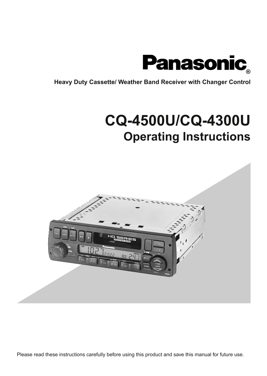
Heavy Duty Cassette/ Weather Band Receiver with Changer Control CQ-4500U/CQ-4300U Operating Instructions Please read these instructions carefully before using this product and save this manual for fut...
Page 2
Panasonic welcomes you to our ever growing family of electronic product owners. We know that this product will bring you many hours of enjoyment. Our reputation is built on precise electronic and mech...
Page 3
Contents Use This Equipment Safely ...................................................................Page 2 ❏Power and Sound Controls ....................................................................
Page 4
Power and Sound Controls BASS/FAD BAL/FADER FEW 4500U Power If the vehicle is not running yet, turn the key in the ignition until the accessory indicator lights. Press [PWR] to switch on the power. Vo...
Page 5
Fader Press the knob to select the FADER mode and then turn it clockwise or counterclockwise to shift the sound volume to the front or rear speakers. or R 1 to 15 Fader Center (F: Front, R: Rear) Note...
Page 6
Radio Basics BASS/FAD BAL/FADER FEW 4500U Mode Selection Press [MODE] to change the operation mode as follows. Radio Cassette CD Changer (when connected) Press and hold [MODE] for more than 2 seconds....
Page 7
Station Preset FM1, FM2, and AM can save maximum 6 stations each in their preset station memories. Caution: To ensure safety, never attempt to preset stations while you are driving. Manual Station Pre...
Page 8
Radio Basics (continued) Tuning in a Weather Band Station Press any of the buttons [1] to [6] to monitor the preset station. The frequency (162) remains unchanged. WB Weather Band Frequency (channel) ...
Page 9
Cassette Tape Player Basics BASS/FAD BAL/FADER FEW 4500U Playing a Cassette Insert the cassette with the exposed tape side facing to the right. Play will start automatically. FEW Playing Side Indicato...
Page 10
Cassette Tape Player Basics (continued) Tape Eject Press [u] to eject the tape, and the previous mode of operation will be resumed. Notes: Always remove the cassette tape from the unit when the casset...
Page 11
TPS Operation (Tape Program Search) Press [3 TPS] to activate the tape program search mode. To select a desired program, press [i] or [j] corresponding times to go backward (up to 8) or forward (up to...
Page 12
Cassette Tape Player Basics (continued) Repeat Play Press [4 REP] to repeat the current program. REPEAT Press [4 REP] again to cancel. Blank Skip Press [5 SKP] to skip unrecorded portions on the tape....
Page 13
CD Changer Basics Note: CD changer functions are designed for an optional CD changer unit. BASS/FAD BAL/FADER FEW 4500U To Start the CD Changer Once the CD changer has been connected, press [MODE] to ...
Page 14
CD Changer Basics (continued) Repeat a Track Press [5] (RPT: REPEAT) to repeat the current selection. "REPEAT" indicator lights. REPEAT Press [5] (RPT: REPEAT) again to cancel. Random Select...
Page 15
Clock Basics (The clock system is 12-hours.) BASS/FAD BAL/FADER FEW 4500U Press and hold Initial Time Press and hold [CLK] to set time display. "AM 12:00" blinks, and the time setting mode i...
Page 16
Clock Basics (continued) Press and hold Alarm Time Setting Press and hold [ALM] to set alarm time Display blinks, and the alarm time setting mode is activated. Press [i] to set the hour. Press [j] to ...
Page 17
Temperature Reading (Only for CQ-4500U) To read the temperatare outside the vehicle, press and hold the Press and hold knob [SEL] for more than 2 seconds. The current temperature in Fahrenheit is disp...
Page 18
In Case of Malfunction Reset Switch If the unit does not respond when the function buttons are pressed, press the reset switch with a small pointed object, such as a pencil point. This will restore th...
Page 19
Installation Guide WARNING This installation information is designed for experienced installers and is not intended for non-technical individuals. It does not contain warnings or cautions of potential...
Page 20
Cut the connector wires one at a time from the ❏Required Tools plug (leaving the leads as long as possible) so You'll need a screwdriver, a 1.5 volt AA battery that you can work with individual leads....
Page 21
Installation Guide (continued) A handy way to identify the speaker leads and Speakers the speaker they connect with is to test the leads Connect the speaker wires. See the wiring using a 1.5 volt AA b...
Page 22
Battery Connect the yellow battery lead to the correct ❏Final Installation radio wire or to the battery fuse port on the fuse Lead Connections block. Connect all wires, making sure that each connectio...
Page 23
Installation Guide (continued) ❏Installation Procedures When bending the mounting tab of the mounting collar with a screwdriver, be careful not to injure your hands and fingers. We strongly recommend ...
Page 24
■Using the Rear Support Strap ■Using the Rubber Cushion (option) (If there is an existing Rear Support Bracket on the fire wall of the vehicle.) Cover Mounting Bolt on the rear of the unit with Rubber...
Page 25
Installation Guide (continued) To Remove the Unit from the vehicle's dashboard Insert each Removal Tool and pull. Removal Tool (U-shaped) Note: Do not lose Removal Tool. They will be needed to remove ...
Page 26
Electrical Connections (Only for CQ-4500U) Cautions: This product is designed to operate with a 12-volt negative ground battery system. To prevent damage to the unit, be sure to follow the connection ...
Page 27
Electrical Connections (continued) (Only for CQ-4300U) Cautions: This product is designed to operate with a 12-volt negative ground battery system. To prevent damage to the unit, be sure to follow the...
Page 28
Troubleshooting ❏Maintenance ❏Notes on Cassette Tapes Your product is designed and manufactured to ensure a minimum of maintenance. Use a Tape Slack: soft cloth for routine exterior cleaning. Never Us...
Page 29
Troubleshooting (continued) ❏Troubleshooting Tips PROBLEM POSSIBLE CAUSE PROBABLE SOLUTION Unit does not turn on. Dead vehicle battery Charge vehicle battery. Ignition or ACC is not on. Turn ignition ...
Page 30
Specifications General Power Supply : 12 V DC (11V-16V) Test Voltage 14.4V, Negative ground Maximum Power Output : 37 W × 4 channels at 400 Hz, Volume Control maximum Power Output : 18 W per channel i...
Page 32
Panasonic Consumer Electronics Company, Division of Matsushita Electric Corporation of America One Panasonic Way, Secaucus, New Jersey 07094 YFM284C331ZA TAMACO0200-0 Printed in Taiwan