Page 1
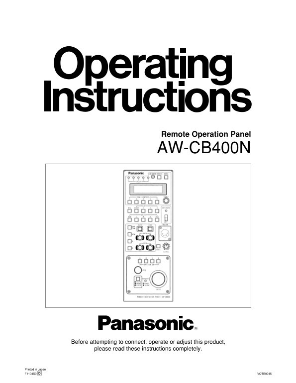
Remote Operation Panel AW-CB400N Before attempting to connect, operate or adjust this product, please read these instructions completely. Printed in Japan F1104S0 VQTB0045D
Page 2
Safety precautions FCC Note: CAUTION This device complies with Part 15 of the FCC Rules. RISK OF ELECTRIC SHOCK To assure continued compliance follow the attached DO NOT OPEN installation instructions...
Page 3
Safety precautions IMPORTANT SAFETY INSTRUCTIONS Read these operating instructions carefully before using the unit. Follow the safety instructions on the unit and the applicable safety instructions li...
Page 4
Contents Introduction ............................................................. Operating procedure ............................................. Turning on the power ................................
Page 5
Precautions for use Handle the ROP carefully. Dropping the ROP or subjecting it to strong impact may give rise to malfunctioning or accidents. Use the ROP in an ambient temperature of 14°F to 113°F (–...
Page 6
Parts and their function Front panel TALLY lamps [1] to [5] MENU button When tally signals are supplied to the (L) tally/INCOM Press this to turn the setting menu ON or OFF. connectors [1] to [5] on t...
Page 7
Parts and their function DTL button BAR/CAM button Each time this is pressed, the detail is switched from ON Use this to select the camera’s video output signals. to OFF or vice versa. While the detai...
Page 8
Parts and their function PED dial INCOM jack This enables the total pedestal of the cameras to be set. The INCOM (inter-communication) headset is connected When exercising control over the AW-E350, AW...
Page 9
Parts and their function Rear panel KCONTROL OUT TO CONTROL PANEL CONTROL OUT TO CAMERA connectors [1] to [5] connector Connect these to the convertible cameras. When connecting the pan/tilt control p...
Page 10
Connections When connecting a convertible camera directly • First, turn off the power of all the equipment before proceeding with the connections. • Use the AW-PS505 for the AC adaptor of the ROP. Con...
Page 11
Example of system configuration When connecting a camera directly Zoom lens Iris control Video signal Convertible camera AW-CA50T8 AW-CA4T1 or AW-CA50T9 + RS-422/RS-232C converter AC adaptor AW-PS505 ...
Page 12
Example of system configuration When connecting the ROP in a system that includes pan/tilt heads, pan/tilt control panel and cable compensation unit Convertible camera Pan/Tilt Head AW-PH400 AW-CA50T8...
Page 13
Example of system configuration When the distance between the ROP and the pan/tilt control panel is more than 10 meters The distance between the ROP and the pan/tilt control panel can be extended up t...
Page 14
Operating procedure Turning on the power Turn on the power. First set the power switch on the AC adaptor used for the ROP and the AC power switches on the cameras to ON, and set the OPERATE switch on ...
Page 15
Operating procedure Sub carrier phase adjustment Select the first camera to be adjusted by pressing the CAM CONTROL button. Press the MENU button to display the menu on the LCD panel. Turn the CONT di...
Page 16
Menu settings Operation method The GAIN information appears first when the OPERATE 1Gain setting switch is set to ON. The gain of the camera selected by the CAM CONTROL button is set on this display. ...
Page 17
Menu settings Items which can be selected on the camera setting display Item Setting Initial value PICTURE LEVEL –50 to +50 LIGHT PEAK/AVG P50 to A50 LIGHT AREA ALL, CENTER, TOP CUT TOP CUT, BTM CUT, ...
Page 18
Menu settings Item Setting Initial value MATRIX G GAIN –127 to +127 MATRIX G PHASE –127 to +127 MATRIX G_Cy GAIN –127 to +127 MATRIX G_Cy PHAS –127 to +127 MATRIX Cy GAIN –127 to +127 MATRIX Cy PHASE ...
Page 19
Menu settings Items which can be selected on the remote operation panel setting display Item Setting Initial value OPTION A OPTION B NOT USE, TELE, WIDE, FAR, NEAR, AF NOT USE OPTION C IR THROUGH, 1/1...
Page 20
How to mount the ROP in a rack <NOTE> The AW-CB400 is 100 mm wide. If it is to be installed in a full-size rack (which accommodates units totaling 420 mm in width), provide panels or other parts...
Page 21
How to change the position of the connector panel The position of the connector panel can be changed from the rear panel to the bottom panel. Screws (!3) Remove the three screws of the bottom and side...
Page 22
Specifications Supply voltage: DC 12.0 V Power consumption: 3.8 W indicates safety information. Input connectors DC 12V IN: XLR, 4 pins GND: GND terminal Output connectors CONTROL OUT TO CONTROL PANEL...
Page 24
PANASONIC BROADCAST & TELEVISION SYSTEMS COMPANY UNIT COMPANY OF MATSUSHITA ELECTRIC CORPORATION OF AMERICA Executive Office: One Panasonic Way 4E-7, Secaucus, NJ 07094 (201) 348-7000 EASTERN ZONE...