Page 1
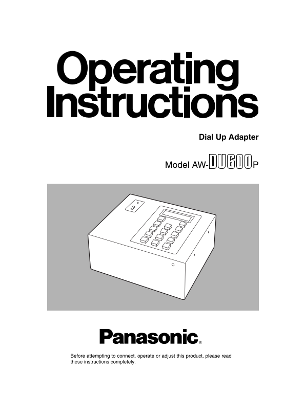
Dial Up Adapter Model AW- Before attempting to connect, operate or adjust this product, please read these instructions completely.
Page 2
FCC Note: CAUTION This device complies with Part 15 of the FCC Rules. RISK OF ELECTRIC SHOCK To assure continued compliance follow the attached DO NOT OPEN installation instructions and do not make an...
Page 3
Contents Introduction . . . . . . . . . . . . . . . . . . . . . . . . . . . . . . . . . . . Menu settings . . . . . . . . . . . . . . . . . . . . . . . . . . . . . . . . . Accessories . . . . . . . . ...
Page 4
Parts and their functions Control panel POWER indicator This lights when power is supplied to the main unit and the POWER switch is set to ON. POWER switch This is the unit’s power switch. LCD panel T...
Page 5
Parts and their functions Rear panel RS-232C CONTROL OUT TO CAMERA & PAN/TILT HEAD TO MODEM INPUT TO RCB/PC DC 12V IN RS-422 CONTROL OUT TO CAMERA & PAN/TILT HEAD TO CONTROL PANEL P5 P4 P3 P2 ...
Page 6
Connections Turn off the power of all components before proceeding with the connections. Transmitting system connections Connect the control panel Coaxial cable (5C-2V) Set the control panel selector ...
Page 7
Connections Transmitting system connection procedure 1. Connect the AW-PS301 AC adapter to the DC 12V IN Set this adapter to switch to an external line via a connector on this adapter. PBX (private br...
Page 8
Connections Receiving system connections Connect the pan-tilt head system to the RS-232C CONTROL OUT connector: When an AW-PH300A is used and the connection distance is 10 m or less: Telephone line Mo...
Page 9
Connections Connect the pan-tilt head system to the RS-422 CONTROL OUT connector: Use the RS-422 connector when the AW-PH350 is to be used as the pan-tilt head or when the connection distance between ...
Page 10
Connections When an AW-PH600 is used and the connection distance is more than 10 m: Telephone line Modem AW-DU600 AW-PS301 AW-CA50D15 (component) AW-CA50A15 (composite) AW-CH600 10 Base-T RS-232C/RS-4...
Page 11
Connections Receiving system connection procedure 1. Connect the AW-PS301 AC adapter to the DC 12V IN 7. Set the power switch on the modem and the pan-tilt connector on this adapter. head to ON. 2. Co...
Page 12
Connections Making a call 5. After control of the pan-tilt head is completed, press the STOP key. Make a call from the AW-DU600 of the transmitting “Hang Up” appears on the LCD display and the system....
Page 13
Connections Direct mode Control the pan-tilt head system directly using this adapter:1. AW-DU600 AW-PS301 AW-CA50T29 (composite) AW-CA50C29 (component) Convertible camera 10 Base-T cable AW-PH350 AW-P...
Page 14
Connections Connection procedure 1. Connect the pan-tilt head system to the CONTROL 5. The pan-tilt head system can be controlled in the OUT connector on this adapter. following ways using the operati...
Page 15
Connections Control the pan-tilt head system using a control panel or PC:2. Coaxial cable (5C-2V) 10Base-T cable AW-PS301 AW-DU600Control panel AW-CA50T29 Convertible camera AW-PH350 AW-PS301 10 Base-...
Page 16
Connections Connection procedure 1. Connect the AW-PS301 AC adapter to the DC 12V IN Set the CONTROL OUT connector according to the connector on this adapter. type of pan-tilt connected and the connec...
Page 17
Menu settings How to perform menu settings Press the key ( START2MENU+ ) and the first menu item will appear on the LCD. Press the key ( START2MENU+ ) while a menu item is displayed on the LCD and the...
Page 18
Menu settings The following items are only displayed when this adapter is in Direct mode This setting selects which connector is to be used for the controller when this adapter is in Direct mode. Menu...
Page 19
Attaching the rack mounting adapters To install the adapter in a rack, use the rack mounting adapters and four of the mounting screws (M4) supplied. Screw Rack mounting adapter Changing the position o...
Page 20
Attaching the joint angle adapter To attach the adapter to the controller, use the joint angle adapter, rack mounting adapter and mounting screws (M4 x 8) supplied. Screw Joint angle adapters Rack mou...
Page 21
Specifications Output connectors: Power supply: DC 10.8V to DC 16V RS-232C CONTROL OUT Power consumption: 5 W TO CAMERA & PAN/TILT HEAD D-sub, 9-pink5 (connect to pan-tilt head) RS-422 CONTROL OUT...
Page 24
PANASONIC BROADCAST & TELEVISION SYSTEMS COMPANY UNIT COMPANY OF MATSUSHITA ELECTRIC CORPORATION OF AMERICA Executive Office: One Panasonic Way 4E-7, Secaucus, NJ 07094 (201) 348-7000 EASTERN ZONE...