Page 1
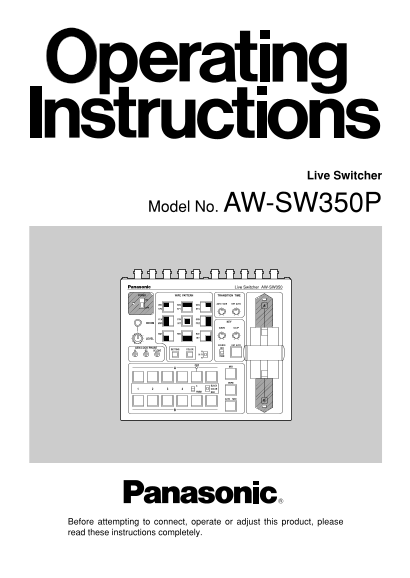
Live Switcher Model No. AW-SW350P Live Switcher AW-SW350 POWER WIPE PATTERN TRANSITION TIME WH1 WH2 WH3 AUTO TAKE KEY AUTO YLW CYN GRN INCOM MWR KEY GAIN CLIP MGT RED BLE LEVEL SOURCE KEY AUTO GEN-LOC...
Page 2
FCC Note: CAUTION This device complies with Part 15 of the FCC Rules. To assure continued RISK OF ELECTRIC SHOCK compliance follow the attached installation instructions and do not make any DO NOT OPE...
Page 3
CONTENTS WARNING/CAUTION FOR SAFETY WARNING WARNING/CAUTION FOR SAFETY Refer all servicing to qualified personnel To reduce the risk of electric shock, don't remove cover or back, unless you are a PRE...
Page 4
Image Transfer, Soft Keys and Linear Keys PREFACE Inside the switcher AW-SW350 has a 1-frame frame memory so that the images created using a personal computer can be captured in this memory through th...
Page 5
EWipe Pattern Selection Switches [WIPE PATTERN] MAJOR OPERATING CONTROLS AND THEIR FUNCTIONS To select a wipe pattern after pressing Wipe Switch y. One of the nine patterns can be selected. The select...
Page 6
INV: This is used to invert the polarity of the key signal. [Example] Selected wipe pattern Use the inversion mode when the input is black text on a white base. Fader lever Normal (N) Reverse (R) Norm...
Page 7
KEY AUTO: This switch is used to set the key synthesis to ON or OFF. Adjusting the horizontal phase: When it is pressed, it lights, and key synthesis is performed for the text, etc. Monitor the wavefo...
Page 8
t Mix Switch [MIX] ■REAR PANEL Press it to switch the signal selected with A-Bus Input Selection Switch } to the signal selected with B-Bus Input Selection Switch q or vice versa by the mix effect. Th...
Page 9
]Y/C Signal Input Jacks [Y/C IN 1, 2, 3, 4, 5] DGenlock Input/BB Output Connector [GLIN/BBOUT] Connect YC signals to these jacks in using them as video input signals. In compliance with the setting of...
Page 10
JUSB port [USB] RBus Selector Switch [BUS A/B /F.F.] Connect one end of the USB cable to this port and the other end to the personal computer This selects the bus switching system. to transfer the ima...
Page 11
■SPECIFICATIONS IMAGE TRANSFER FUNCTION In order for the host computer to run the USB image transfer program used with the AW-SW350, it must satisfy the following system requirements. The AW-SW350 Liv...
Page 12
■INSTALLING THE DEVICE DRIVER When the screen for specifying the driver loading directory appears as shown in Fig.3, This section describes how to install the device driver used with the USB image tra...
Page 13
■INSTALLING THE APPLICATION PROGRAM In order to confirm that the device driver has been installed successfully, it is This section describes how to install the application program used with the USB im...
Page 14
■OPERATION METHOD The installer program shown in Fig.7 now starts. Proceed with the installation by This section describes how to operate the application program used with the USB image following the ...
Page 15
<When the image is larger than the number of pixels that can be displayed> When the target image appears in the image display area, specify the start or cutout Drag the frame displayed in the sc...
Page 16
— When images could not be transferred — Click the “RAM” radio button or “RAM+ROM” radio button to select the type of memory If an error resulted or images could not be transferred because a cable was...
Page 17
■CONNECTION FOR EXTERNAL SYNCHRONIZATION CONNECTIONS (Frame Synchronizer OFF) ●Adjust the horizontal and color phases of the cameras. ●For installation and connection, be sure to ask the store where y...
Page 18
■CONNECTION TO PERSONAL COMPUTER Camera VIDEO OUT Convertible Camera AW — E600 Convertible Camera AW — E600 VIDEO OUT Windows PC Convertible Camera AW — E600 Color monitors Camera or character generat...
Page 19
■EXAMPLE FOR THE CONNECTION WITH PAN/TILT HEADS AND CONTROL PANEL ●The cameras can be locally controlled by using the pan/tilt head AW-PH300A, multi-hybrid control panel AW-RP505, and multi-port hub A...
Page 20
RACK MOUNTING INFORMATION RELATED TO SYSTEM UPGRADES ■RACK MOUNTING (1) Switcher phases ●Do not mount the Live Switcher on a closed rack or bookshelf. 1) Video signal output phase (frame synchronizer ...
Page 21
Operating temperature range: 32˚F to 104˚F (0˚C to 40˚C) SPECIFICATIONS/STANDARD ACCESSORIES Humidity: 30% to 90% Dimensions (W!H!D): 8-1/4”!3-7/16”!6-15/16” (210!86!176 mm) Weight: Approx. 4.9 lb (2....
Page 23
PANASONIC BROADCAST & TELEVISION SYSTEMS COMPANY DIVISION OF MATSUSHITA ELECTRIC CORPORATION OF AMERICA Executive Office: 3330 Cahuenga Blvd W., Los Angeles, CA 90068 (323) 436-3500 EASTERN ZONE: ...