# A B C D E F G H I J K L M N O P Q R S T U V W X Y Z

Panasonic AN8011S User Guide and Manual

Summary

This advanced two-channel DC-DC converter control IC unit is designed for precise and reliable power management in sensitive electronic devices. Featuring high-speed 500 kHz PWM control and independent outputs, it ensures optimized operation while incorporating essential protections like short-circuit prevention and under-voltage lockout. The comprehensive manual provides engineers with detailed pin descriptions, electrical characteristics, timing diagrams, and functional application examples, making it ideal for designing stable power systems for LCD displays, digital cameras, and portable devices (PDAs).
📄 Preview PAGE OF 16

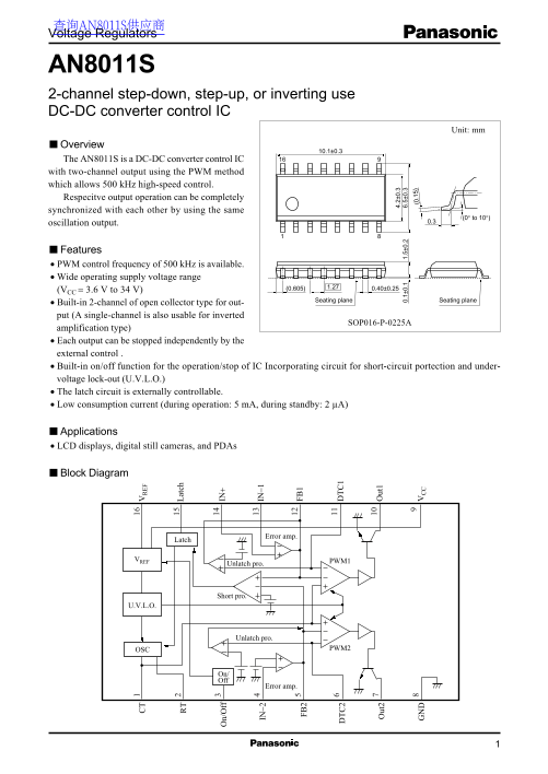
Page 1 Text Content

查询AN8011S供应商 Voltage Regulators

AN8011S 2-channel step-down, step-up, or inverting use DC-DC converter control IC

Unit: mm

Overview

The AN8011S is a DC-DC converter control IC with two-channel output using the PWM method

at ch

which allows 500 k Hz high-speed control. Respecitve output operation can be completely synchronized with each other by using the same

(0° to 10°)

oscillation output. IN 0.3

n/ ff

Features

IN −2 IN −1

PWM control frequency of 500 k Hz is available. Wide operating supply voltage range

(VCC = 3.6 V to 34 V)

FB Seating plane Seating plane

Built-in 2-channel of open collector type for out- FB put (A single-channel is also usable for inverted

SOP016-P-0225A

amplification type) Each output can be stopped independently by the external control . Built-in on/off function for the operation/stop of IC Incorporating circuit for short-circuit portection and under- voltage lock-out (U.V.L.O.) ut ut The latch circuit is externally controllable.

Low consumption current (during operation: 5 m A, during standby: 2 µA) 0. 1± 0. 1. 5± 0. 6. 5± 0.

Applications LCD displays, digital still cameras, and PDAs

Block Diagram

Error amp.

Latch

VREF PWM1

Unlatch pro.

Short pro.

Unlatch pro.

OSC PWM2

On/ Off

Error amp.

Page Summary Contents For Panasonic AN8011S User Guide and Manual

Page 1 查询AN8011S供应商 Voltage Regulators AN8011S 2-channel step-down, step-up, or inverting use DC-DC converter control IC Unit: mm Overview The AN8011S is a DC-DC converter control IC with two-channel output ...
Page 2 AN8011S Voltage Regulators Pin Descriptions Pin No. Symbol Description CT Pin for connecting the oscillation frequency setting capacitor for triangular oscillation circuit. Frequecy of triangular osci...
Page 3 Voltage Regulators AN8011S Absolute Maximum Ratings at Ta = 25°C Parameter Symbol Rating Unit Supply voltage VCC Power dissipation * PD m W Operating ambient temperature Topr −30 to +85 °C Storage tem...
Page 4 AN8011S Voltage Regulators Electrical Characteristics(continued) at VCC = 12 V, Ta = 25°C Parameter Symbol Conditions Min Typ Max Unit PWM comparator 1/2 block High-level input threshold voltage VDT-H...
Page 5 Voltage Regulators AN8011S Terminal Equivalent Circuits Pin No. Equivalent circuit Description I/O VREF The terminal used for connecting a timing capacitor to set oscillator frequency. Use a To PWM in...
Page 6 AN8011S Voltage Regulators Terminal Equivalent Circuits (continued) Pin No. Equivalent circuit Description I/O VREF FB2: The output terminal of ch.2 error amplifier. 25 µA typ. Its source current is −...
Page 7 Voltage Regulators AN8011S Terminal Equivalent Circuits (continued) Pin No. Equivalent circuit Description I/O Out1: Out1 The ch.1 open collector type (darlington) output terminal. The absolute maximu...
Page 8 AN8011S Voltage Regulators Terminal Equivalent Circuits (continued) Pin No. Equivalent circuit Description I/O Latch: VREF Terminal for connecting the time constant setting capacitor for timer latch s...
Page 9 Voltage Regulators AN8011S ut pu t f re qu en cy k H z) ef er en ce ol ta ge ut pu t f re qu en cy k H z) Application Notes [1] Main characteristics Reference voltage temperature characteristics Maxim...
Page 10 AN8011S Voltage Regulators Application Notes (continued) [2] Function descriptions 1. Reference voltage block This block is composed of the band gap circuit, and outputs the temperature compensated 2....
Page 11 Voltage Regulators AN8011S Application Notes (continued) [2] Function descriptions (continued) 4. Timer latch short-circuit protection circuit This circuit protects the external main swiching devices,...
Page 12 AN8011S Voltage Regulators Application Notes (continued) [3] The time constant setting method for timer latch type short-circuit protection circuit (continued) ICHG 80 µA typ. FB2 SW1 Latch comp. 4.2 ...
Page 13 Voltage Regulators AN8011S Application Notes (continued) [5] Triangular wave oscillation circuit Oscillation frequency setting method The waveform of triangular wave oscillation is obtained by chargin...
Page 14 AN8011S Voltage Regulators Application Notes (continued) [7] Timing chart Supply voltage (VCC) 3.1 V typ. Reference voltage (VREF) Lock-out release Error amplifier output (FB) Power supply Triangular ...
Page 15 Voltage Regulators AN8011S Application Circuit Examples kΩ Application circuit example 1 at ch 7 kΩ n/ ff IN −2 IN −1 120 kΩ VCC FB FB 7V SBD 3 V 5 V 0. µF 0. µF f = 200 k Hz Error Duty = 75% 25.5 kΩ ...
Page 16 AN8011S Voltage Regulators Application Circuit Examples Application circuit example 2 VIN = 7 V at ch 2.5 V 120 kΩ VCC = 7 V 10 µF n/ ff IN −2 IN −1 Error amp. Latch FB FB VREF Unlatch pro. PWM1 Short...

Manual Details

Brand Panasonic
Pages 16
File Size 169.84 KB
Published June 05, 2026
49 views

Enter the captcha to get the download link:

captcha

Frequently Asked Questions

What is the typical PWM control frequency?

The AN8011S supports a PWM control frequency of 500 kHz.

How can I set the dead-time period for the outputs?

For both channels, the dead-time period (DTC) can be set by connecting an external resistor to pins 6 (DTC2) and 11 (DTC1).

Where does the power supply voltage need to be connected?

The main power supply voltage is applied to pin 9 (V_CC).

Does the IC have built-in protection features?

Yes, it incorporates circuits for short-circuit protection and Under-Voltage Lockout (U.V.L.O.).