Panasonic WVCP474H User Guide and Manual
Summary
This comprehensive manual details the features and specifications of the Panasonic WV-CP474H Color CCTV Camera, designed for advanced video surveillance. It covers essential operating functions like auto light control and digital motion detection, serving as a vital guide for installers and users to ensure proper setup and optimal performance.
Page 1 Text Content
FEATURES
1. The following functions are built in. (1) Auto Light Control (ALC)/Electronic Light Control (ELC) (2) The SUPER-D2 function eliminates interference by strong background lighting Color CCTV Camera which makes the camera picture dark, such as a spotlight. Dynamic range of 46 d B. (3) Internal Line-locked Multiplex Vertical (VD2) Sync. Operating Instructions (4) Auto/Manual White Balance Function (5) Electronic Shutter Function 2. Signal-to-noise ratio of 50 d B (Equivalent to AGC Off) 3. Minimum Illumination of 0.8 lx (0.08 foot-candle) at color mode, 0.1 lx (0.01 foot-candle) at black and white mode with F1.4 lens.
Model No. WV-CP474H 4. 480 lines of horizontal resolution
5. High quality picture: (a) 2H type vertical enhancer for greater picture sharpness (b) Chroma averaging circuit for better color signal-to-noise ratio (c) Minimum of aliasing on fine objects
(Lens: Option)
(d) Expanded dynamic range by use of knee circuit (e) Highlight aperture correction for greater picture detail of bright objects
Before attempting to connect or operate this product,
6. Ability to shoot indoor scenes with fixed iris lens by use of Electronic Light Control (ELC)
please read these instructions carefully and save this manual for future use.
function. 7. Selectable electronic sensitivity enhancing modes including AUTO, MANUAL and OFF 8. Built-in Digital Motion Detector
N1002-0 3TR001320AAA Printed in Japan
9. Auto black-and-white mode enables the camera to switch between color and black- and-white picture in response to light input.
For U.S.A
NOTE: This equipment has been tested and found to comply with the limits for a Class A digital device, pursuant to Part 15 of the FCC CAUTION Rules. These limits are designed to provide reasonable protection against harmful interfer-
RISK OF ELECTRIC
ence when the equipment is operated in a
SHOCK DO NOT OPEN
commercial environment. This equipment gen- erates, uses, and can radiate radio frequency energy and, if not installed and used in accor- CAUTION: TO REDUCE THE RISK OF ELECTRIC SHOCK, dance with the instruction manual, may cause
MAJOR OPERATING CONTROLS AND THEIR FUNCTIONS
harmful interference to radio communications.
DO NOT REMOVE COVER (OR BACK).
Operation of this equipment in a residential
NO USER-SERVICEABLE PARTS INSIDE. REFER SER-
area is likely to cause harmful interference in
VICING TO QUALIFIED SERVICE PERSONNEL. which case the user will be required to correct uoy
the interference at his own expense.
FCC Caution: To assure continued compli-
The lightning flash with arrow-
ance, (example - use only shielded interface Color CCTV Camera
head symbol, within an equilat- Model No. WV-CP474H
cables when connecting to computer or POWER 24V~60Hz 4.3W VIDEO OUT 1V[p-p] 75Ω
eral triangle, is intended to Monufochured by Matsushita
peripheral devices). Any changes or modifica- Communication industrial SET
alert the user to the presence Co.Ltd. Yokohama Japan tions not expressly approved by the party Made in Japan FOR COMMERDAL USE ONLY
of uninsulated "dangerous volt- responsible for compliance could void the Day / GND DUT
Night ALARM GNDIN
age" within the product's enclo- user’s authority to operate this equipment. POWER
SA 1965 sure that may be of sufficient
magnitude to constitute a risk
of electric shock to persons. The serial number of this product may be found on the top of the unit.
The exclamation point within You should note the serial number of this unit an equilateral triangle is intend- in the space provided and retain this instruction !3 !2 ed to alert the user to the pres- as a permanent record of your purchase to aid ence of important operating identification in the event of theft. and maintenance (servicing)
instructions in the literature Model No. WV-CP474H
accompanying the appliance. !0
Serial No. SA 1966
WARNING: To prevent fire or electric shock hazard, do not expose this appliance to rain or moisture.
The apparatus shall not be exposed to dripping or splashing and that no objects filled with liq- uids, such as vases, shall be placed on the apparatus.
PREFACE
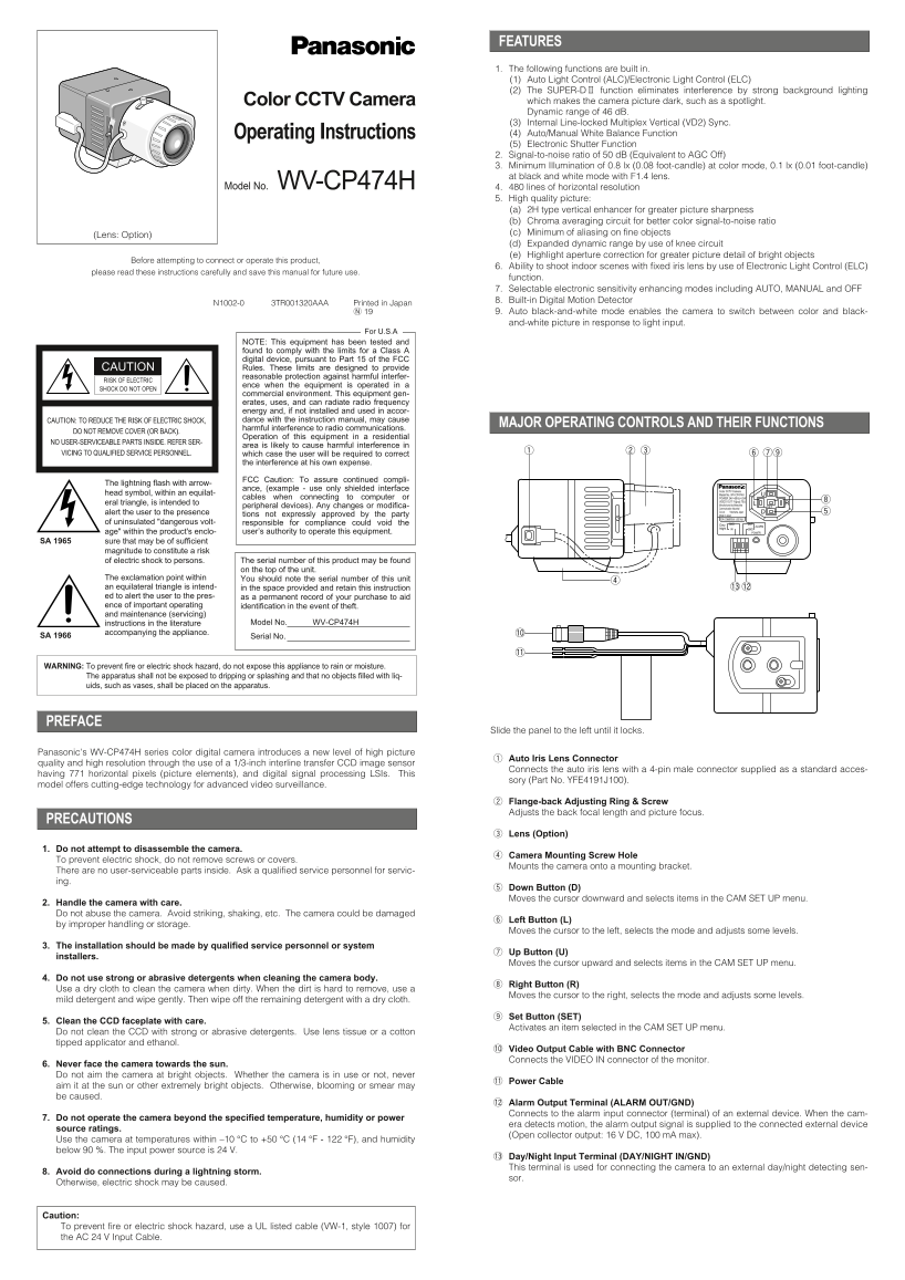
Slide the panel to the left until it locks.
Panasonic's WV-CP474H series color digital camera introduces a new level of high picture
Auto Iris Lens Connector
quality and high resolution through the use of a 1/3-inch interline transfer CCD image sensor
Connects the auto iris lens with a 4-pin male connector supplied as a standard acces-
having 771 horizontal pixels (picture elements), and digital signal processing LSIs. This
sory (Part No. YFE4191J100).
model offers cutting-edge technology for advanced video surveillance.
Flange-back Adjusting Ring & Screw Adjusts the back focal length and picture focus.
PRECAUTIONS
Lens (Option)
1. Do not attempt to disassemble the camera.
Camera Mounting Screw Hole
To prevent electric shock, do not remove screws or covers.
Mounts the camera onto a mounting bracket.
There are no user-serviceable parts inside. Ask a qualified service personnel for servic- ing.
Down Button (D) Moves the cursor downward and selects items in the CAM SET UP menu.
2. Handle the camera with care. Do not abuse the camera. Avoid striking, shaking, etc. The camera could be damaged
Left Button (L)
by improper handling or storage.
Moves the cursor to the left, selects the mode and adjusts some levels.
3. The installation should be made by qualified service personnel or system
Up Button (U)
installers.
Moves the cursor upward and selects items in the CAM SET UP menu.
4. Do not use strong or abrasive detergents when cleaning the camera body.
Right Button (R)
Use a dry cloth to clean the camera when dirty. When the dirt is hard to remove, use a
Moves the cursor to the right, selects the mode and adjusts some levels.
mild detergent and wipe gently. Then wipe off the remaining detergent with a dry cloth.
Set Button (SET)
5. Clean the CCD faceplate with care.
Activates an item selected in the CAM SET UP menu.
Do not clean the CCD with strong or abrasive detergents. Use lens tissue or a cotton tipped applicator and ethanol.
!0 Video Output Cable with BNC Connector Connects the VIDEO IN connector of the monitor.
6. Never face the camera towards the sun. Do not aim the camera at bright objects. Whether the camera is in use or not, never
!1 Power Cable
aim it at the sun or other extremely bright objects. Otherwise, blooming or smear may be caused.
!2 Alarm Output Terminal (ALARM OUT/GND) Connects to the alarm input connector (terminal) of an external device. When the cam-
7. Do not operate the camera beyond the specified temperature, humidity or power
era detects motion, the alarm output signal is supplied to the connected external device
source ratings.
(Open collector output: 16 V DC, 100 m A max).
Use the camera at temperatures within –10 °C to +50 °C (14 °F - 122 °F), and humidity below 90 %. The input power source is 24 V.
!3 Day/Night Input Terminal (DAY/NIGHT IN/GND) This terminal is used for connecting the camera to an external day/night detecting sen-
8. Avoid do connections during a lightning storm.
Otherwise, electric shock may be caused.
Caution: To prevent fire or electric shock hazard, use a UL listed cable (VW-1, style 1007) for the AC 24 V Input Cable.
Page Summary Contents For Panasonic WVCP474H User Guide and Manual
Manual Details
| Brand | Panasonic |
|---|---|
| Pages | 6 |
| File Size | 206.78 KB |
| Published | June 15, 2026 |
Enter the captcha to get the download link:

Frequently Asked Questions
What is the minimum illumination in color mode?
0.8 lx (0.08 foot-candle) with F1.4 lens.
How does the SUPER-D2 function help?
It eliminates interference by strong background lighting that makes the picture dark, achieving a dynamic range of 46 dB.
What are the power specifications?
24 V AC 60 Hz, 4.3 W.
What safety precaution is mentioned to prevent electric shock?
Do not remove screws or covers; no user-serviceable parts inside. Also, do not expose to rain or moisture.