# A B C D E F G H I J K L M N O P Q R S T U V W X Y Z

Panasonic AN8013SH User Guide

Summary

This specialized single-channel PWM DC-DC converter control IC is designed for creating high-efficiency step-up or step-down regulated voltages, ideal for miniature and portable power supply units. The AN8013SH offers a wide operating range (3.6 V to 34 V) and robust features including built-in overcurrent and under-voltage protection. This manual serves as comprehensive technical documentation, providing detailed pin descriptions, electrical characteristics, and complete application examples necessary for integrating the IC into advanced power electronics designs.
📄 Preview PAGE OF 15

Page 1 Text Content

查询AN8013SH供应商 Voltage Regulators

AN8013SH Single-channel step-up or step-down DC-DC converter control IC

Unit: mm

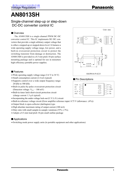
Overview The AN8013SH is a single-channel PWM DC-DC converter control IC. This IC implements DC-DC con- verters that provide a single arbitrary output voltage that is either a stepped-up or stepped-down level. It features a wide operating supply voltage range, low power, and a built-in overcurrent protection circuit to protect the switching transistor from damage or destruction. The AN8013SH is provided in a 0.5 mm pitch 10-pin surface mounting package and is optimal for use in miniature

high-efficiency portable power supplies.

Features

SSOP010-P-0225

Wide operating supply voltage range (3.6 V to 34 V)

Small consumption current (2.4 m A typical)

Pin Descriptions

Supports control over a wide output frequency range: 20 k Hz to 500 k Hz.

CLM VCC

Built-in pulse-by-pulse overcurrent protection circuit RT Out

CT GND

(Detection voltage: VCC − 100 m V)

S.C.P. IN−

Built-in timer latch short-circuit protection circuit

DTC FB

(charge current 1.3 µA typical)

Incorporating the under-voltage lock-out (U.V.L.O.) circuit 0. Built-in reference voltage circuit (Error amplifier reference input: 0.75 V (allowance: ±4%)) 0. 5± 0. 0. 5± 0. 0. 2± 0.

Output block is open-collector (darlington) type.

High absolute maximum rating of output current (100 m A) Duty ratio with small sample-to-sample variations (55% ± 5%).

Adopts a 0.5-mm lead pitch 10-pin small outline package

Applications Switching mode power supply units (in portable equipment and other applications)

Page Summary Contents For Panasonic AN8013SH User Guide

Page 1 查询AN8013SH供应商 Voltage Regulators AN8013SH Single-channel step-up or step-down DC-DC converter control IC Unit: mm Overview The AN8013SH is a single-channel PWM DC-DC converter control IC. This IC impl...
Page 2 AN8013SH Voltage Regulators Block Diagram 0.1 V Out VREF RT S R Latch RT VREF Error amp. S.C.P. comp. IN− 0.75 V S R Latch Absolute Maximum Ratings at Ta = 25°C Parameter Symbol Rating Unit Supply vol...
Page 3 Voltage Regulators AN8013SH Electrical Characteristics at Ta = 25°C Parameter Symbol Conditions Min Typ Max Unit U.V.L.O. block Circuit operation start voltage VUON 2.8 3.1 3.4 Hysteresis width VHYS m...
Page 4 AN8013SH Voltage Regulators Electrical Characteristics at Ta = 25°C (continued) Parameter Symbol Conditions Min Typ Max Unit Short-circuit protection circuit block Input threshold voltage VTHPC 0.70 0...
Page 5 Voltage Regulators AN8013SH Terminal Equivalent Circuits (continued) Pin No. Pin I/O Function Internal equivalent circuit S.C.P. Connection for the capacitor that determines the time constant for soft...
Page 6 AN8013SH Voltage Regulators sc ill at or re qu en cy k H z) In pu t t hr es ho ld ol ta ge Terminal Equivalent Circuits (continued) Pin No. Pin I/O Function Internal equivalent circuit Out Open-collec...
Page 7 Voltage Regulators AN8013SH To ta l c on su pt io cu rr en In pu t t hr es ho ld ol ta ge Application Notes (continued) [1] Main characteristics (continued) Input threshold voltage line regulation Tot...
Page 8 AN8013SH Voltage Regulators Application Notes [2] Function descriptions 1. Reference voltage block The reference voltage block is based on a band gap circuit, and outputs a temperature corrected refer...
Page 9 Voltage Regulators AN8013SH Application Notes (continued) [2] Function descriptions (continued) 6. PWM comparator The PWM comparator controls the output pulse on-period according to the input voltage....
Page 10 AN8013SH Voltage Regulators Application Notes (continued) [3] Triangular wave oscillation circuit 1. Setting the oscillator frequency The waveform of triangular wave oscillation is obtained by chargin...
Page 11 Voltage Regulators AN8013SH Application Notes (continued) [4] Setting the dead-time (maximum duty) (continued) CT waveform VCTH DTC VDTC VRT IDTC = [A] waveform IDTC RT 3.6 PWM CT FB t OFF t ON Off Of...
Page 12 AN8013SH Voltage Regulators Application Notes (continued) [5] Setting the time constant of the timer latch short-circuit protection circuit (continued) ICHG is the constant current determined by the o...
Page 13 Voltage Regulators AN8013SH Application Notes (continued) [6] Timing chart VCC (0 V→3.6 V) rise time tr (VCC) ≥ 10 [µs] Supply voltage (VCC) 3.1 V typ. Lock-out Internal reference voltage release Erro...
Page 14 AN8013SH Voltage Regulators Application Circuit Examples 1. Step-down circuit In Out ut ut f = 200 k Hz Dumax = 80% RDTC = 110 kΩ .C .P IN .C .P IN 2. Step-up circuit In Out +12 V f = 200 k Hz Dumax =...
Page 15 Voltage Regulators AN8013SH Application Circuit Examples (continued) 3. On/off circuit example 1) Cutting the power supply line In VO On/off ut ut Standby current ≈ 0 µA 2) Cutting the IC VCC line In ...

Manual Details

Brand Panasonic
Pages 15
File Size 152.84 KB
Published June 17, 2026
1 views

Enter the captcha to get the download link:

captcha

Frequently Asked Questions

What is the supply voltage range for the AN8013SH?

The operating supply voltage range is 3.6 V to 34 V.

How to implement a standby function for this IC?

Add an external circuit, such as inserting a switch in the power supply line or between VCC pin and power supply.

What is the max oscillator frequency of the AN8013SH?

The maximum oscillation frequency is 500 kHz.

What protection features does this IC have?

It has overcurrent protection, timer latch short-circuit protection, and under-voltage lock-out circuit.