Page 1
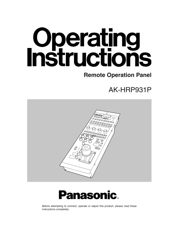
Remote Operation Panel AK-HRP931P Before attempting to connect, operate or adjust this product, please read these instructions completely.
Page 2
Safety precautions FCC Note: This device complies with Part 15 of the FCC Rules. CAUTION To assure continued compliance follow the attached RISK OF ELECTRIC SHOCK installation instructions and do not ...
Page 3
Contents Overview ......................................................................................................................................................................... Accessories ...
Page 4
Operating precautions The panel’s power is supplied from the camera control unit (AK-HCU931P). Handle the panel carefully. Dropping the panel or subjecting it to strong impact may cause malfunctioning...
Page 5
Parts and their functions ROP operation panel Camera power switch indicator This indicates whether the camera power is ON or OFF. When any of the panel switches is pressed, the buzzer sounds. Lights u...
Page 6
Parts and their functions 2Auto black balance switch [AUTO BLACK] 1Optical transmission alarm indicator [OPT ALARM] This is used to automatically adjust the black balance. This is the optical transmis...
Page 7
Parts and their functions CONTROL 15600K switch [5600K MODE] SHADING WHITE BLK BLACK WHITE KNEE CLIP GAMMA UNDO This is used to change the amplification rate of the GBR signals by an electrical circui...
Page 8
Parts and their functions VPAR: Vertical parabola correction MPNT This is used to correct the coloring of black screen images This adjusts the master knee point in the range of 110% to in the vertical...
Page 9
Parts and their functions 9Flare control switch [FLARE CONTROL] <HDTV detail control switch [HD.DTL] This is selected to change the amount of flare correction. This switch is selected to change the...
Page 10
Parts and their functions –CLP: Detail edge undershoot clip CRSP: Skin tone detail crisp This is used to limit the length of the undershoot parts of This is used to remove the very faint noise compone...
Page 11
Parts and their functions +CLP: Detail edge overshoot clip MTX 12, GAIN, PHASE This is used to limit the length of the overshoot parts of the These are used to select the following 12-axis matrix deta...
Page 12
Parts and their functions DCLK: Down-conversion link SCCO (SDTV): Subcarrier phase coarse adjustment This is used to decide whether to go with the down- This is used to coarsely adjust the phase of th...
Page 13
Parts and their functions POWER (FAN): Fan power switch FILTER ND HEAD CC This is used to set the power of the camera head’s fan to CAP 6.3 1.6 4.3 6.33.2 DFO ON, OFF, or AUTO. SCENE FILE MONITOR SEQ ...
Page 14
Parts and their functions Calling scene file data 1. From among the 1 to 8 scene file switches, press the number of the switch that corresponds to the scene file -6 -3 which is to be called and light ...
Page 15
Parts and their functions R, G, B gain controls [R, G, B GAIN] Iris/master pedestal control joystick [IRIS/PED] These are used for the red (R), green (G) and blue (B) The iris level of the lens is adj...
Page 16
Parts and their functions ROP connector panel CCU connector The camera control unit (CCU) is connected here. RCP connector The remote control panel (RCP) is connected here. PREVIEW RCP CCU Preview con...
Page 17
External dimension drawings ROP ON HEAD ON VFPW CAMERA NO. SD CARD CLOSE BAR TEST WHITE SET UPBLACK CHARACTER RST OPT ALARMAUTO FAN 60Hz CABLE FLARE BLK GAMMA AUTO MODE KNEE WHITE MATRIX HD. DTL SD. D...
Page 18
PANASONIC BROADCAST & TELEVISION SYSTEMS COMPANY UNIT COMPANY OF MATSUSHITA ELECTRIC CORPORATION OF AMERICA Executive Office: One Panasonic Way 4E-7, Secaucus, NJ 07094 (201) 348-7000 EASTERN ZONE...