Panasonic AKHBU931P User Guide
Summary
The AK-HBU931P Build-up Unit enhances the functionality of the AK-HC931P multi-format camera by enabling the attachment of a large lens for expanded operational range. This comprehensive manual is essential reading for technicians and professional photographers, detailing everything from safety precautions (electrical shock/fire hazards) to advanced system operation. It provides step-by-step guides on controls, connections, mounting, and optimal maintenance care, ensuring safe and efficient use in studio or field environments.
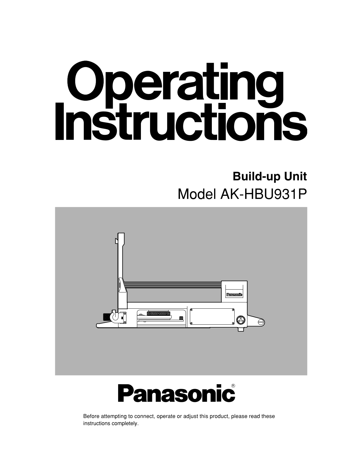
Page 1 Text Content
Build-up Unit
Model AK-HBU931P
Before attempting to connect, operate or adjust this product, please read these instructions completely.
Page Summary Contents For Panasonic AKHBU931P User Guide
Page 1
Build-up Unit Model AK-HBU931P Before attempting to connect, operate or adjust this product, please read these instructions completely.
Page 2
Safety precautions FCC Note: CAUTION This device complies with Part 15 of the FCC Rules. RISK OF ELECTRIC SHOCK To assure continued compliance follow the attached DO NOT OPEN installation instructions...
Page 3
Contents Safety precautions . . . . . . . . . . . . . . . . . . . . . . . . . . . . . . . . . . . . . . . . . . . . . . . . . . . . . . . . . . . . . . . . . . . . . . . . .2 Overview . . . . . . . . ...
Page 4
Controls and their functions Front Panel Top Panel Lens guide Camera mounting base The 2/3z box-type lens is attached by hooking it onto this This is used to attach the camera. For details, refer to g...
Page 5
Controls and their functions Bottom Panel Right Side Panel Screw hole for mounting tripod (3/8-16UNC) Hook for securing cable This is used to attach the unit to a tripod or other The optical fiber cab...
Page 6
Controls and their functions Left Side Panel Operation panel MAIN OUT(200VA)ACBREAKER ALARM 12OV AC 80Hz RESET CCU Cable clamp VF power switch [VF POWER] This is used to clamp the optical fiber cable ...
Page 7
Controls and their functions 4:3 MARKER switch RET B switch [RET B] This is the 4:3 marker ON/OFF switch. When the 4:3 This is used to select the RET B switch. When it is marker is ON, the brightness ...
Page 8
Mounting methods Mounting the lens Mounting the camera Mount the camera on the camera mounting base, and U-shaped groove slide the camera toward the front along the groove until it Lens guide clicks i...
Page 9
Connections Connect the multi-format camera (and lens) to the build-up unit as shown in the figure below. Connect the cable from the CCU to the connector on the build-up unit. Connect the cable of the...
Page 10
External dimension drawings VF POWER TALLY MARKER CENTER ON/OFF CURSOR RET A RET B USER SEL ON VF MARKER H–POSI V–POSI WIDTH HEIGHT VF DETAIL Y/G MONI SEL EXT OFF FILTER PIPMENU SELECT LOCAL x0.8 ND C...
Page 11
Specifications Power supply: AC 220 V (supplied from CCU) Power consumption: 8 W (main unit only) 1indicates safety information. Switch functions: AC OUT reset, viewfinder power, front tally ON/OFF, C...
Page 12
PANASONIC BROADCAST & TELEVISION SYSTEMS COMPANY UNIT COMPANY OF MATSUSHITA ELECTRIC CORPORATION OF AMERICA Executive Office: 3330 Cahuenga Blvd W., Los Angeles, CA 90068 (323) 436-3500 EASTERN ZO...
Manual Details
| Brand | Panasonic |
|---|---|
| Pages | 12 |
| File Size | 316.31 KB |
| Published | July 22, 2026 |
0 views
Enter the captcha to get the download link:
