ON Semiconductor MBR2030CTL SWITCHMODE Dual Schottky Power Rectifier Data Sheet User Guide
Summary
This high-efficiency Schottky rectifier is designed for robust power supply and management applications requiring reliable current conversion. Featuring a dual configuration, low forward voltage drop, and high surge capacity across a wide temperature range, it ensures stable performance even under demanding conditions. This technical manual provides comprehensive data sheets, including detailed electrical characteristics, thermal parameters (junction-to-ambient), and application guidelines for design engineers and power electronics professionals integrating this component into their systems.
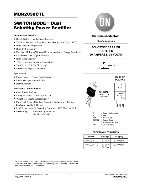
Page 1 Text Content
MBR2030CTL
SWITCHMODE™ Dual Schottky Power Rectifier Features and Benefits Highly Stable Oxide Passivated Junction
http://onsemi.com
Very Low Forward Voltage Drop (0.4 Max @ 10 A, TC = 150°C) High Junction Temperature
SCHOTTKY BARRIER
High dv/dt Capability
RECTIFIER
Excellent Ability to Withstand Reverse Avalanche Energy Transients
20 AMPERES, 30 VOLTS
Low Power Loss / High Efficiency High Surge Capacity 175°C Operating Junction Temperature 20 A Total (10 A Per Diode Leg) 2, 4 Pb−Free Package is Available*
Applications Power Supply − Output Rectification MARKING
DIAGRAM
Power Management − ORING Instrumentation
Mechanical Characteristics
Case: Epoxy, Molded TO−220AB
CASE 221A
Epoxy Meets UL 94 V−0 @ 0.125 in B2030LG
PLASTIC
Weight: 1.9 Grams (Approximately) Finish: All External Surfaces Corrosion Resistant and Terminal Leads are Readily Solderable Lead Temperature for Soldering Purposes: 260°C Max. for 10 Sec ESD Rating: Human Body Model 3B
= Assembly Location
Machine Model C
= Year
WW = Work Week B2030L = Device Code
= Pb−Free Package
AKA = Diode Polarity
ORDERING INFORMATION
Device Package Shipping
MBR2030CTL TO−220 50 Units/Rail
MBR2030CTLG TO−220 50 Units/Rail
(Pb−Free)
*For additional information on our Pb−Free strategy and soldering details, please download the ON Semiconductor Soldering and Mounting Techniques Reference Manual, SOLDERRM/D.
Semiconductor Components Industries, LLC, 2006 Publication Order Number: July, 2006 − Rev. 4 MBR2030CTL/D
Page Summary Contents For ON Semiconductor MBR2030CTL SWITCHMODE Dual Schottky Power Rectifier Data Sheet User Guide
Manual Details
| Brand | Dual |
|---|---|
| Pages | 5 |
| File Size | 54.76 KB |
| Published | May 30, 2026 |
Enter the captcha to get the download link:

Frequently Asked Questions
What is the maximum operating junction temperature?
The device has an Operating Junction Temperature range of -65 to +175 °C.
Is the component suitable for Pb-Free applications?
Yes, a Pb−Free Package (MBR2030CTLG) is available.
What is the maximum nonrepetitive surge current?
The maximum nonrepetitive peak surge current is 150 A FSM.
What voltage rate of change can this rectifier withstand?
It has a rated Voltage Rate of Change (R) capability of 1000 V/µs.