OMRON Timer Counter H3CR-F -G -H Solid State Timer H3CR-F H3CR-H Power OFF Delay Time Relay User Manual
Summary
This technical guide introduces a highly reliable electronic time relay designed for precise timing in industrial automation systems. The manual serves as an essential resource, detailing step-by-step installation procedures, comprehensive wiring schematics, and thorough safety precautions for expert users. It covers all operational parameters, including voltage ranges, power consumption, and specific load requirements, making it the definitive reference point for engineers and technicians setting up or servicing control circuits that require accurate time-delayed switching.
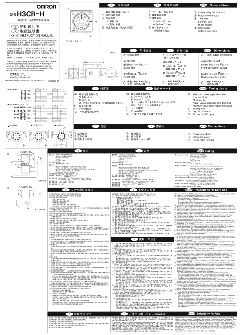
Page 1 Text Content
UK/USA Nomenclature
POWER
OFF Output relay ON indicator
Ry ON DELAY
H3CR-H 0.3 Rated time selector 0.2 0.4
Time unit
OFF 0.1 0.5
sec S series: sec 0.6 min M series: min
Setting dial
(setting time value)
UK/USA INSTRUCTION MANUAL
UK/USA Dimensions
A Panel cutout dimensions
Thank you for purchasing this OMRON product. This manual Applicable socket
primarily describes precautions required in installing and
63.7 P2CF-08, P2CF-11 Model P2CF-08, P2CF-11 wiring the timer. Before operating the product ,read this 0.7 P2CF-08, P2CF-11
manual thoroughly to acquire sufficient knowledge of the Front connection socket
product. Keep this manual for future reference.
44.8 P3G-08, P3GA-11
P3G-08, P3GA-11 Model P3G-08, P3GA-11 © All Rights Reserved Back connection socket
www.fa.omron.co.jp 2256879-0A
* H3CR-H8(R)L * : H3CR-H8(R)L * : H3CR-H8(R)L ** H3CR-HRL ** : H3CR-HRL ** : H3CR-HRL
Rt t Rt H3CR-H8L UK/USA Timing charts
Rt: Rt: Minimum power application time
S 0.1 S series; 0.1s
M 2 M series; 2s
(Ry ON) M ; 2s
Note: Less application time than this
H3CR-H8RL(-HRL )2
Rt t Rt ON minimum values may cause no output.
t: t: Setting time
*1: (Ry on)
*1: (Ry on) *1: (Ry ON) indicator
*2: -HRL
*2: -HRL *2: Pin No. of -HRL type
(Ry ON)
H3CR-H8L H3CR-H8RL H3CR-HRL
UK/USA Connections
Delayed contacts Operating power Force-reset terminal
UK/USA Rating C
H3CR-H□ RL
AC100/110/120V 50/60Hz AC100/110/120V 50/60Hz Rated supply voltage • 100 to 120 VAC (50/60 Hz) AC200/220/240V 50/60Hz AC200/220/240V 50/60Hz • 200 to 240 VAC (50/60 Hz) AC/DC24V 50/60Hz AC/DC24V 50/60Hz • 24 VAC/VDC (50/60 Hz) DC48V DC48V • 48 VDC, DC100 125V DC100 125V • 100 to 125 VDC
Operating voltage range
H3CR-A 85% to 110% of rated supply voltage
Power consumption
AC200/220/240V 0.35VA/0.30W AC240V • 100 to 120 VAC: approx. 0.23 VA (0.22 W) at 120 VAC
AC200/220/240V 0.35VA/0.30W AC240V
AC100/110/120V 0.23VA/0.22W AC120V • 200 to 240 VAC: approx. 0.35 VA (0.3 W) at 240 VAC
AC/DC24V 0.17VA/0.15W AC24V 1.0W DC24V AC100/110/120V 0.23VA/0.22W AC120V
• 24 VAC/DC: approx. 0.17 VA (0.15 W) at 24 VAC
DC100 125V 0.50W DC125V AC/DC24V 0.17VA/0.15W AC24V 1.0W DC24V
approx. 0.1 W at 24 VDC
DC48V 0.18W DC48V DC100 125V 0.50W DC125V
• 48 VDC: approx. 0.18 W at 48 VDC
DC48V 0.18W DC48V
• 100 to 125 VDC: approx. 0.5 W at 125 VDC
AC250V/DC30V 5A Operation start voltage : 30% max. of rated supply voltage
cosφ AC250V/DC30V 5A
Control outputs (Time limit contacts): 5 A at 250 VAC / 30 VDC
H3CR-H8RL DC5V 100m A cosφ
resistive load (cosφ = 1)
H3CR-H8L/-HRL DC5V 10m A H3CR-H8RL DC5V 100m A Minimum load: • 10 m A at 5 VDC for H3CR-H8L/-HRL (failure level: P)
H3CR-H8RL H3CR-H8L/-HRL DC5V 10m A
• 100 m A at 5 VDC for H3CR-H8RL (failure level: P) Ambient temperature (Operating): −10°C to 55°C (with no icing) • Storage: −25°C to 65°C (with no icing) Ambient humidity Operating: 35% to 85%
H3CR-H□ RL
UK/USA Precautions for Safe Use
Please comply strictly with the following instructions which are intended to ensure safe operation of the controller. (1) (1) Make sure the proper product is specified for the application.
(2) For correct use, do not subject the timer to the following conditions.
• Dramatic temperature fluctuations • High humidity or where condensation may occur • Severe vibration and shock • Where excessive dust, corrosive gas, or direct sunlight may be present • Where there is danger of splashing of water, oil or any chemicals (3) Store the Timer within the rated ranges given for the Timer model you are using. If the Timer is stored (3) 10 below −10°C, allow it to warm up for three hours at room temperature before turning ON the power supply. (3) 10 (4) Mounting the Time Switch side-by-side may reduce the life expectancies of internal components. H3CR-H8RL (5) Use the Timer within the ambient operating temperature and ambient operating humidity ranges
given for the Timer model you are using.
(6) Separate the Timer from any sources of excessive static electricity, such as forming materials
(5) (6) and pipes carrying power or liquid materials.
(6) (7) Maintain the variations in the power supply voltage to within the specified allowable range.
(7) (8) If a voltage that exceeds the rating is applied, internal components may be destroyed.
(8) (9) Wire all terminals correctly.
(9) (10) Do not wire the terminals which are not used.
(8) (11) Install and clearly label a switch or circuit breaker so that the operator can quickly turn OFF the power supply.
(9) (11) OFF (12) The exterior of the Timer may be damaged by organic solvents (such as thinners or benzene), (10) strong alkali, or strong acids. (13) Confirm that the power and output indicators are operating normally. Depending on the
(11) OFF (12)
operating environment, the indicators and plastic parts may deteriorate faster than expected,
(12) · causing the indicators to fail. Periodically perform inspections and replacements.
(13) / LCD LCD/ (13) / LCD (14) When disposing of the Timer, observe all local ordinances as they apply.
LCD/ (15) When using the Timer in an area with excessive electronic noise, separate the Timer and input
device as far as possible from the noise sources. It is also recommended to shield the input
(14) signal wiring to prevent electronic interference.
(15) (16) Cleaning
Do not use paint thinner or the equivalent. Use standard grade alcohol to clean the product. (16) (17) Do not change the time range while the Timer is in operation, otherwise the Timer may malfunction. Be sure that the Timer is out of operation before changing the setting. (18) Power supply connection
(17) Use a DC power supply having a ripple factor of 20% or less and supplying a mean voltage
(1) that is within the rated operating voltage marked on the timer. (18) Make sure that the supply voltage is applied to the timer all at once, using contacts such as of a switch or relay. Otherwise, the timer may not be able to perform power reset or its set time may be up when it should not.
(19) Please do not exceed the voltage rating marked on the timer. If voltage other than the rated voltage is applied, the internal components may be damaged.
(20) Input connection (19) When connecting the contact or transistor for external input signal to the input terminals of the timer, pay
(4) attention to the following points to prevent short-circuiting of the transformerless power supply. DC 20 If a relay or a transistor is connected as an external signal input to a Timer (ex. H3CR-A),
(20) whose power supply terminal is a common terminal for input signal, and the H3CR-H,
short-circuit current is generated. Be sure to input for each Timer from an independent isolated relay or isolate the power supply
(5) of either of those Timers. (6) For the power supply of an input device, use an isolation transformer(*2), of which the primary
H3CR-A H3CR-H H3CR and secondary windings are mutually isolated and the secondary winding is not grounded. (*3)
(21) To the input signal terminals of the Timer, an appropriate input is applied when the specified (*2) H3CR-A H3CR-H terminals are short-circuited. Do not attempt to connect any input terminal to any terminal other than the input terminal or to
apply voltage across other than the specified input terminals.
(21) Otherwise, the internal circuit of the Timer may be damaged.
The H3CR-H has a large inrush current. Provide sufficient power supply capacity. (7) If the power supply capacity is too small, there may be delays in turning ON the output. The H3CR-H uses a latching relay for the output. Shock, such as dropping the H3CR-H
H3CR-H ON
during shipment or handling, can cause the output contacts to reverse to the neutral position.
H3CR-H H3CR-H
Check the output status with a tester before using the H3CRH. (22) As the H3CR-H has a high impedance circuit, it may sometimes not be reset by the interference
H3CR-H
(22) H3CR-H of induced voltage. To prevent such trouble, wire the lead as short as possible and avoid laying wires in parallel with power lines. (23) In case the induced voltage exceeds 30% of the rated voltage (10% for DC type), connect a CR filter
(23) 30% 10% (8) H3CR-H (C=0.1 μF, R=120 Ω approx) or a bleeder resistor across the power supply terminals of the timer.
CR C = 0.1 μF, R = 120Ω) Also, when there is residual voltage across the power supply terminals, connect a bleeder
(24) H3CR-H resistor in the same manner.
(9) 30 DC CR (24) Do not use the H3CR-H under the conditions below since they may cause malfuntion.
C=0.1μF R=120Ω Time expiration operation within 3 seconds max. repeat frequency.
Force-reset within 3seconds max. repeat frequency.
(25) EN/IEC (10) H3CR-H (25) EN/IEC Standard Compliance
EMC Refer to the datasheet for the H3CR for cable selection and other conditions for compliance class A with EMC standards. (11) EN/IEC This is a class A product. In residential areas it may cause radio interference, in which case EMC the user may be required to take adequate measures to reduce interference. The power supply terminals and input terminals are not isolated. There is basic insulation class A between the power supply terminals and output terminals. IEC60664 If double or reinforced insulation is required, use the double or reinforced insulation defined in IEC 60664 that is suitable for the maximum applied voltage for the clearance, solid insulation, and other factors.
IEC60664
UK/USA Suitability for Use
OMRON shall not be responsible for conformity with any standards, codes, or regulations that apply to the combination of the products in the customer's application or use of the product. Take all necessary steps to determine the suitability of the product for the systems, machines, and a) equipment with which it will be used. Know and observe all prohibitions of use applicable to this b) product. NEVER USE THE PRODUCTS FOR AN APPLICATION INVOLVING SERIOUS RISK c) TO LIFE OR PROPERTY WITHOUT ENSURING THAT THE SYSTEM AS A WHOLE HAS BEEN d) 24 DESIGNED TO ADDRESS THE RISKS, AND THAT THE OMRON PRODUCT IS PROPERLY e) a) d) RATED AND INSTALLED FOR THE INTENDED USE WITHIN THE OVERALL EQUIPMENT OR SYSTEM. See also Product catalog for Warranty and Limitation of Liability.
Page Summary Contents For OMRON Timer Counter H3CR-F -G -H Solid State Timer H3CR-F H3CR-H Power OFF Delay Time Relay User Manual
Manual Details
| Brand | Omron |
|---|---|
| Pages | 2 |
| File Size | 742.11 KB |
| Published | June 05, 2026 |
Enter the captcha to get the download link:

Frequently Asked Questions
What are the ambient temperature and humidity limits for operation?
The operating environment is specified as -10°C to 55°C (with no icing) and 35% to 85% humidity.
How often should I inspect or replace the unit's components?
Because indicators and plastic parts may deteriorate, period inspections and replacements are necessary. Also, output relays have limited operational life cycles.
What must be done when applying power for the first time?
Always install and clearly label a switch or circuit breaker so that the operator can quickly turn OFF the unit if an issue occurs.
Are there restrictions on using the output relays?
Yes, ensure they are used within their rated load, power supply, and mechanical life expectancy.