Omron H3CA Solid-state Timer User's Manual
Summary
The OMRON H3CA is a compact, multi-mode solid-state timer designed for industrial control applications requiring precise timing of coils and loads. This manual provides detailed instructions on setup, wiring configurations (including mechanical and electronic delays), operation modes, and comprehensive safety information. It is essential reading for technicians and engineers utilizing DIN rail mounted timers who need reliable functionality across a wide range from 0.1 seconds to 9,990 hours.
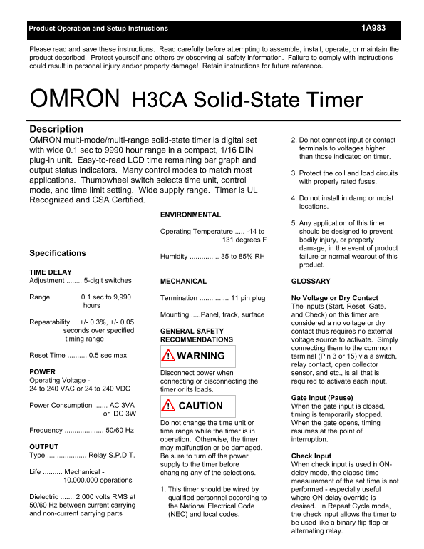
Page 1 Text Content
Product Operation and Setup Instructions 1A983
Please read and save these instructions. Read carefully before attempting to assemble, install, operate, or maintain the product described. Protect yourself and others by observing all safety information. Failure to comply with instructions could result in personal injury and/or property damage! Retain instructions for future reference.
OMRON H3CA Solid-State Timer Description
OMRON multi-mode/multi-range solid-state timer is digital set 2. Do not connect input or contact terminals to voltages higher
with wide 0.1 sec to 9990 hour range in a compact, 1/16 DIN
than those indicated on timer.
plug-in unit. Easy-to-read LCD time remaining bar graph and output status indicators. Many control modes to match most
3. Protect the coil and load circuits
applications. Thumbwheel switch selects time unit, control with properly rated fuses. mode, and time limit setting. Wide supply range. Timer is UL
4. Do not install in damp or moist
Recognized and CSA Certified.
locations.
ENVIRONMENTAL
5. Any application of this timer
Operating Temperature ..... -14 to should be designed to prevent 131 degrees F bodily injury, or property
damage, in the event of product
Specifications
Humidity ............... 35 to 85% RH failure or normal wearout of this
product.
TIME DELAY Adjustment ........ 5-digit switches MECHANICAL GLOSSARY
Range .............. 0.1 sec to 9,990 Termination ............... 11 pin plug No Voltage or Dry Contact hours The inputs (Start, Reset, Gate,
Mounting .....Panel, track, surface and Check) on this timer are
Repeatability ... +/- 0.3%, +/- 0.05 considered a no voltage or dry seconds over specified GENERAL SAFETY contact thus requires no external timing range RECOMMENDATIONS voltage source to activate. Simply
connecting them to the common
Reset Time .......... 0.5 sec max. WARNING! terminal (Pin 3 or 15) via a switch,
relay contact, open collector
POWER Disconnect power when sensor, and etc., is all that is Operating Voltage - connecting or disconnecting the required to activate each input. 24 to 240 VAC or 24 to 240 VDC timer or its loads.
Gate Input (Pause)
Power Consumption ....... AC 3VA CAUTION! When the gate input is closed, or DC 3W timing is temporarily stopped.
Do not change the time unit or When the gate opens, timing
Frequency .................... 50/60 Hz time range while the timer is in resumes at the point of
operation. Otherwise, the timer interruption.
OUTPUT may malfunction or be damaged. Type .................... Relay S.P.D.T. Be sure to turn off the power Check Input
supply to the timer before When check input is used in ON-
Life .......... Mechanical - changing any of the selections. delay mode, the elapse time 10,000,000 operations measurement of the set time is not
1. This timer should be wired by performed - especially useful
Dielectric ....... 2,000 volts RMS at qualified personnel according to where ON-delay override is 50/60 Hz between current carrying the National Electrical Code desired. In Repeat Cycle mode, and non-current carrying parts (NEC) and local codes. the check input allows the timer to
be used like a binary flip-flop or alternating relay.
Page Summary Contents For Omron H3CA Solid-state Timer User's Manual
Manual Details
| Brand | Omron |
|---|---|
| Pages | 9 |
| File Size | 73.55 KB |
| Published | May 27, 2026 |
Enter the captcha to get the download link:

Frequently Asked Questions
What is the operating temperature range for the H3CA timer?
The operational temperature range is -14 to 131 degrees F.
How do I wire a load using internal output relays (H3CA-8)?
Connect the load to separate power source then DC wire the load, utilizing Figure D for guidance.
What input are used to initiate or stop timing?
The Start, Reset, and Gate inputs can be utilized through specific terminal pairs (e.g., Pins 3 & 7 is Reset Input).