OMRON Timer Counter Digital Controller E5AK E5AK-T Instruction Manual (ENG JPN)
Summary
This comprehensive manual provides detailed guidance for operating and installing the robust E5AK-T digital controller. Designed for precise control in complex industrial environments, this unit manages diverse process data via multiple analog/digital inputs and controls systems using versatile outputs, supporting both ON/OFF and PID methods. The guide covers everything from safety precautions and wiring schematics to environmental specifications and troubleshooting error codes. It is essential reading for automation engineers and technicians responsible for the setup, calibration, and maintenance of automated industrial control systems.
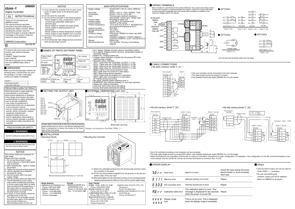
Page 1 Text Content
WIRING TERMINALS
NOTICE MAIN SPECIFICATIONS
Basic insulation is used between the outputs (Between relay output and analog output)
E5AK-T Supply voltage AC100-240V (-15% to +10%), 50/60 Hz, If reinforced insulation is required between the outputs, connect to a device that does ●OPTION1
9. If you remove the controller from its case, never
16VA not have exposed chargeable parts and whose basic insulation is suitable for the
Digital Controller touch nor apply shock to the electronic parts SDA
and power AC24V (-15% to +10%), 50/60Hz, 12VA maximum voltage used in the outputs.
inside. consumption DC24V (-15% to +10%), 8W
10. Do not cover the controller. Input Thermocouple, platinum resistance
INSTRUCTION MANUAL EN
11. Do not use the controller in the following places: thermometer, current input, voltage input EV1 SD RDA
AC100-240V
- Places subject to icing, condensation, dust or Control output According to output unit
Thank you for purchasing this 50/60Hz EV2 RD RDB
Auxiliary output 1a AC 250 V, 3A (resistive load)
corrosive gas (especially sulfide gas or
OMRON product. 16VA
Control method ON/OFF or PID control COM SG SG
ammonia gas) OPTION2
This manual primarily describes Ambient temperature -10 to 55°C (For UL3121-1, IEC/EN61010-1, or SOURCE
- Places subject to vibration and large shocks OPTION1 Event input1/2 RS-232C RS-422 RS-485
precautions required installing and Surrounding Air Temperature:50°C) AC/DC24V
- Places subject to splashing liquid or oil Ambient humidity 35 to 85%
operating the digital controller. Before 50/60Hz E5AK-T□B□ E5AK-T□01□ E5AK-T□02□ E5AK-T□03□
atmosphere Storage temperature -25 to 65°C OUT1
operating the product, read this 12VA, 8W
- Places subject to intense temperature changes Weight Approx. 450 g
manual thoroughly to acquire sufficient
- Places subject to heat radiation from a furnace. Enclosure ratings Front panel : NEMA4 for indoor use (IP66
CT ●OPTION3
knowledge of the product. Keep this equivalent) ●OPTION2
12. Be sure to wire properly with correct polarity of OUT2
manual for future reference. Setup environment Installation category II, Pollution degree 2. OPTION3
terminals.
(Conforming to IEC/EN61010-1, UL3121-1, CSA C22.2 No.1010.1)
13. Avoid wiring near high voltage sources and power
Altitude 2000m max.
SUB1 EV3
OMRON Corporation lines carrying large currents. Recommended fuse T2A, AC250V, Time-lag, Low-breaking
capacity RSP EV4
SUB2 4-20m A COM
m A Transfer output
To ensure safe and correct use of this Event input3/4
• No.1 display: Displays process values or parameter symbol.
NAMES OF PARTS ON FRONT PANEL
• No.2 display: Displays present set point, manipulated variable or Pt TC E5AK-T□F□
product, also read the following E5AK-T□B□
manuals: parameter settings. • Pattern No.: Displays pattern No..
• E5AK-T Digital Controller Program status PV No.1 display
• Program status indicators: Indicate how the present-SP of the
indicators • Do not wire the terminals which are not used.
User’s Manual
operating step changes.
The above manuals can be obtained 8.8.8.8
SVPTN Pattern No. • Operation status indicators
from any OMRON sales office or PTN TIMEBar graph - OUT1: Lights when the “CONTROL OUTPUT 1” is ON.
8.8.8.87 - OUT2: Lights when the “CONTROL OUTPUT 2” is ON. CABLE CONNECTIONS
dealer. RMT HOLD MANU SUB1 SUB2
Operation status
OUT1 OUT2 RST AT WAIT - SUB1: Lights when the “AUXILIARY OUTPUT 1” is ON.
indicators No.2 display • RS-232C interface: E5AK-TM01M
UNPACKING OUT1 OUT2 - SUB2: Lights when the “AUXILIARY OUTPUT 2” is ON.
SUB1 SUB2 RUN - MANU: Lights in the manual operation mode. Make sure that the package contains the RST
MANU RMT
- RST: Lights when the control is in reset status. Host computer E5AK-T
following items. If all the items are not in HOLD RST
WAIT AT - RMT: Lights during remote operation. • Only one controller can be connected to the host computer.
the package or an item is damaged, RS-232C:25P
- HOLD: Lights when the program is in hold status. • The cable length should not exceed 15 meters.
contact your dealer immediately. - WAIT: Lights when the program is in wait status. RS-232C
• Use shielded twisted pair leads (AWG28 min.) for the cables.No.
Up key Display key RUN/RESET key - AT: Flashes during auto-tuning. 1 FG No.
Down key
• E5AK-T • Bar graph: Displays pattern elapseing time %.
RUN/RST 2 SD 20 SD
• RUN/RESET key: Switches between run and reset operation.
• Mounting bracket 3 RD
• Display key: Selects parameters. 19 RD
• Instruction Manual
• Down key: Each press returns the setting. 4 RS 18 SG
• Up key: Each press advances the setting. 5 CS
PRECAUTIONS IN USING THE PRODUCT
6 DR
When the product is used under the SETTING THE OUTPUT UNIT EXTERNAL DIMENSIONS (unit: mm)
circumstances or environment 20 ER
Shielded
below,ensure adherence to limitations 7 SG
cable
of the ratings and functions.Also,take
[OUT] PV
countermesures for safety precautions
such as fail-safe installations.
E53-S 8.8.8.8 • Use under circumstances or OUT1 E53-Q SVPTN
environment which are not described E53-Q3 PTN TIME
in the instruction manual. E53-Q4 OUT2 8.8.8.87
• RS-422 interface: E5AK-TM02M • RS-485 interface:E5AK-TM03M
RMT HOLD MANU SUB1 SUB2
• Use for nuclear power control, railway, E53-C3
OUT1 OUT2 RST AT WAIT
E53-C3D Host computer
aircraft, vehcle, incinerator, medical Host computer
E53-V34 E5AK-T(No.0) E5AK-T(No.30) RS-485 A<B:"1" Mark
equipment,entertainment RUN
E53-V35 Shielded cable A>B:"0" Space
RST RS-422 RS-422
equipment,safety device etc... RS-422
• Use for applications where death or No. Terminator ×2 No.
Shielded cable
serious property damage is possible Bracket E5AK (240Ω 1/2W)
RDA 32 SDA 32 SDA
and extensive safety precautions are Terminator(120Ω 1/2W)
RDB 31 SDB 31 SDB
required.
Press down on the hook on the top of the front panel SDA 19 RDA 19 RDA
Watertight packing FG
E5AK-T(No.0) E5AK-T(No.30)
(part pointed with an arrow in the above drawing) and
SDB 20 RDB 20 RDB
PRECAUTIONS ON SAFETY RS-485 RS-485
turn a screwdriver to loosen the screw on the lower Setting is not required on the E5AK-TPRR□□ 18 SG 18 SG
part of the front panel. No. No.
WARNING FG
INSTALLATION
Incorrect handling may cause death or injury.
• Mounting Panels • Mounting the Controller
110 min.Unit (mm) 20 B 20 B
WARNING
Do not touch the terminals while the power is ON. This may cause an electric shock.
NOTICE • Up to 32 controllers including a host computer can be connected .
Items shown below are necessary for • The total cable length should not exceed 500 meters. Use shielded twisted pair leads (AWG28 min.) for the cables. safe usage. • Attach terminators to the controllers at both ends of a series of controllers connected in an open configuration. For example, in the configuration on the left, connect terminators to the
120 min. +0.8
Please note them carefully. 0
host computer and the unit No.30, and do not connect terminators to connector Nos. 0 to 29.
1. Do not use the product in place where explosive or flammable gases may be present.
+0.8 ERROR DISPLAY Others 2. Never disassemble , repair or modify 0
the product.
(1) Attach the watertight packing from the terminal side and then insert • Only the E53-R output unit can be used for
3. Tighten the terminal screws properly.
Check the input wiring (incorrect,
4. Use the specified size solderless the controller to the panel. E5AK-TPRR□□ controllers.
Input error Input is in error. disconnected, or short-circuited),
terminals for wiring. (2) Fit the mounting bracket (supplied) into the grooves on the top and
• No user serviceable parts.
5. Use the product within the rated input type .
Recommended panel thickness is 1 to 8 mm. bottom sides of the rear case.
supply voltage. However, Output unit can be replaced.
(3) Alternately tighten the top and bottom screws on the mounting bracket
6. Use the product within the rated load. Internal memory is in error. Repair.
Memory error Return to OMRON for all repairs.
7. The life expectancy of the output applying equal pressure a little at a time until the rachet rotates freely.
relay varies considerably according
North America Europe Asia / Pacific
to its the output relay within its rated Internal circuits are in error. Repair.
OMRON ELECTRONICS LLC OMRON EUROPE B.V. 欧姆龍(中国)有限公司 (中国) OMRON ASIA-PACIFIC PTE LTD. A/D converter error
load and electrical life expectancy, if
Phone:1-847-843-7900 (EUROPEAN H.Q.) Phone: (8610)8391-3005 (Singapore)
the output relay is used beyond its
OMRON CANADA INC. Phone: 31-23-56-81-300 歐姆龍亞洲有限公司 (香港) Phone: 65-6835-3011 The calibration data is in error. This
life expectancy, its contacts may
Phone: 1-416-286-6465 Fax : 31-23-56-81-388 Phone: 852-2375-3827 OMRON ELECTRONICS PTY.LTD.
become fused or burned. Calibration data error message is displayed for two seconds Repair.
8. A switch or circuit breaker should be Phone : 1-514-636-6676 台灣歐姆龍股有限公司總公司(台灣) (AUSTRALIA)
when the power is turned ON.
provided close to this unit. (French Language) Phone: 886-2-2715-3331 Phone: 02-9878-6377
The switch or circuit breaker should 韓国OMRON株式会社(大韓民国)
be within easy reach of the operator, Phone: 82-2-512-0871(Korean) Display range This is not an error. This is displayed
and must be marked as a Phone: 82-2-549-2766 over when the display range is exceeded. disconnecting means for this unit. (English/Japanese)
Page Summary Contents For OMRON Timer Counter Digital Controller E5AK E5AK-T Instruction Manual (ENG JPN)
Manual Details
| Brand | Omron |
|---|---|
| Pages | 2 |
| File Size | 651.88 KB |
| Published | June 05, 2026 |
Enter the captcha to get the download link:

Frequently Asked Questions
What is the recommended total cable length for installation?
The total cable length should not exceed 500m. Use shielded twisted pair leads (AWG28 or greater).
Where can this controller NOT be used?
Do not use it in places subject to icing, condensation, dust, corrosive gas, intense temperature changes, high voltage sources, or near carrying large currents.
How do I calculate the required load capacity for relays?
The output relay life is greatly affected by opening/closing capacity and conditions, so operate within specified electrical lifespan cycles.
What are the necessary terminal connections for communication?
If linking multiple units (1:N connection), up to 32 devices can be connected using the RS-485 interface. Only ends of the transmission path need a terminator.