# A B C D E F G H I J K L M N O P Q R S T U V W X Y Z

National Semiconductor LMC6462 Dual LMC6464 Quad Data Sheet

Summary

This micropower CMOS operational amplifier delivers reliable, high-performance amplification with guaranteed rail-to-rail input/output capabilities. Featuring ultra-low supply current and minimal offset voltage, it is optimized for demanding low-voltage environments. Ideal for medical devices, battery-powered systems, and portable communication equipment, the comprehensive manual details its full electrical characteristics, operational ranges, and packaging options to ensure seamless circuit integration.
📄 Preview PAGE OF 18

Page 1 Text Content

LM ual/LM uad icropow er,R ail-to-R ail Input and utput perational plifier

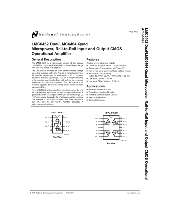
LMC6462 Dual/LMC6464 Quad Micropower, Rail-to-Rail Input and Output CMOS Operational Amplifier General Description Features The LMC6462/4 is micropower version of the popular (Typical unless otherwise noted) LMC6482/4, combining Rail-to-Rail Input and Output Range Ultra Low Supply Current µA/Amplifier with very low power consumption. Guaranteed Characteristics at 3V and 5V The LMC6462/4 provides an input common-mode voltage Rail-to-Rail Input Common-Mode Voltage Range range that exceeds both rails. The rail-to-rail output swing of Rail-to-Rail Output Swing the amplifier, guaranteed for loads down to kΩ, assures (within m V of rail, VS

5V and RL kΩ)

maximum dynamic sigal range. This rail-to-rail performance

Low Input Current f A

of the amplifier, combined with its high voltage gain makes it

Low Input Offset Voltage 0.25 m V

unique among rail-to-rail amplifiers. The LMC6462/4 is an excellent upgrade for circuits using limited common-mode

range amplifiers. Applications The LMC6462/4, with guaranteed specifications at 3V and Battery Operated Circuits 5V, is especially well-suited for low voltage applications. Transducer Interface Circuits

quiescent power consumption of µW per amplifier (at VS Portable Communication Devices 3V) can extend the useful life of battery operated systems. Medical Applications The amplifier’s f A input current, low offset voltage of Battery Monitoring 0.25 m V, and d B CMRR maintain accuracy in battery-powered systems.

8-Pin DIP/SO 14-Pin DIP/SO

DS012051-1

DS012051-2

National Semiconductor Corporation DS012051 www.national.com

Page Summary Contents For National Semiconductor LMC6462 Dual LMC6464 Quad Data Sheet

Page 1 LM ual/LM uad icropow er,R ail-to-R ail Input and utput perational plifier LMC6462 Dual/LMC6464 Quad Micropower, Rail-to-Rail Input and Output CMOS Operational Amplifier General Description Features T...
Page 2 Ordering Information Package Temperature Range NSC Transport Military Industrial Drawing Media −55˚C to +125˚C −40˚C to +85˚C 8-Pin Molded DIP LMC6462AMN LMC6462AIN, LMC6462BIN N08E Rails 8-Pin SO-8 L...
Page 3 Absolute Maximum Ratings (Note 1) Operating Ratings (Note 1) If Military/Aerospace specified devices are required, Supply Voltage 3.0V V+ 15.5V please contact the National Semiconductor Sales Office/ ...
Page 4 5V DC Electrical Characteristics (Continued) Unless otherwise specified, all limits guaranteed for TJ 25˚C, V+ 5V, V− 0V, VCM VO V+/2 and RL 1M. Boldface limits apply at the temperature extremes. LMC6...
Page 5 5V AC Electrical Characteristics Unless otherwise specified, all limits guaranteed for TJ 25˚C, V+ 5V, V− 0V, VCM VO V+/2 and RL 1M. Boldface limits apply at the temperature extremes. LMC6462AI LMC646...
Page 6 3V AC Electrical Characteristics Unless otherwise specified, V+ 3V, V− 0V, VCM VO V+/2 and RL 1M. Boldface limits apply at the temperature ex- tremes. LMC6462AI LMC6462BI LMC6462AM Symbol Parameter Co...
Page 7 Typical Performance Characteristics VS +5V, Single Supply, TA 25˚C unless otherwise specified (Continued) Sinking Current vs Input Voltage Input Voltage Noise Output Voltage Noise vs Frequency vs Inpu...
Page 8 Typical Performance Characteristics VS +5V, Single Supply, TA 25˚C unless otherwise specified (Continued) Gain and Phase vs Slew Rate vs Non-Inverting Large Capacitive Load Supply Voltage Signal Pulse...
Page 9 Typical Performance Characteristics VS +5V, Single Supply, TA 25˚C unless otherwise specified (Continued) Inverting Large Signal Inverting Large Signal Inverting Small Signal Pulse Response Pulse Resp...
Page 10 Application Information Another circuit, shown in Figure 6, is also used to indirectly (Continued) drive capacitive loads. This circuit is an improvement to the circuit shown in Figure because it prov...
Page 11 Application Information (Continued) DS012051-14 FIGURE 10. Non-Inverting Configuration Offset Voltage Adjustment DS012051-12 FIGURE 8. Canceling the Effect of Input Capacitance 6.0 Spice Macromodel Sp...
Page 12 Application Information board at all, but bend it up in the air and use only air as an in- (Continued) sulator. Air is an excellent insulator. In this case you may have to forego some of the advantage...
Page 13 Application Information cations that benefit from these features include analytic (Continued) medical instruments, magnetic field detectors, gas detectors, 8.0 Instrumentation Circuits and silicon-bas...
Page 14 Typical Single-Supply Applications TRANSDUCER INTERFACE CIRCUITS DS012051-25 DS012051-22 FIGURE 19. Full-Wave Rectifier FIGURE 16. Photo Detector Circuit with Input Current Protection (RI) Photocells ...
Page 15 Typical Single-Supply Applications LOW FREQUENCY NULL (Continued) where ∆t is the time the amplifier input takes to move from 1.67V to 3.33V. The calculations are shown below. where RC 0.68 seconds →t...
Page 16 Physical Dimensions inches (millimeters) unless otherwise noted 8-Pin Small Outline Package Order Number LMC6462AIM or LMC6462BIM NS Package Number M08A 14-Pin Small Outline Package Order Number LMC64...
Page 17 Physical Dimensions inches (millimeters) unless otherwise noted (Continued) 8-Pin Molded Dual-In-Line Package Order Number LMC6462AIN or LMC6462BIN NS Package Number N08E 14-Pin Molded Dual-In-Line Pa...
Page 18 LM ua l/L ua ic ro po er ,R ai l-t o- ai l I np ut an ut pu pe ra tio na pl ifi er Notes LIFE SUPPORT POLICY NATIONAL’S PRODUCTS ARE NOT AUTHORIZED FOR USE AS CRITICAL COMPONENTS IN LIFE SUPPORT DEVIC...

Manual Details

Brand National
Pages 18
File Size 648.70 KB
Published June 18, 2026
5 views

Enter the captcha to get the download link:

captcha

Frequently Asked Questions

Is this Op Amp suitable for battery-operated systems?

Yes, it has a quiescent power consumption of 60 μW per amplifier at Vcc = 3V.

Does the LMC6462/4 support rail-to-rail output?

Yes, it assures rail-to-rail output swing for loads down to 25 kΩ.

What is the input current draw during operation?

It features a low input current of 150 fA, which assists in accuracy.

Are there variations available for extreme temperature environments?

Military versions are rated for operational temperatures from -55˚C to +125˚C.