# A B C D E F G H I J K L M N O P Q R S T U V W X Y Z

Motorola Semiconductor MC6800 User's Guide and Manual

Summary

Explore comprehensive hardware details and programming information for the M68000 family of embedded microprocessors, including MC68HC000, MC68EC000, and MC68SEC000. This manual is essential for engineers developing sophisticated, power-efficient systems. It covers core architectural features, low-power design implementation (e.g., static selectable buses), and guaranteed object-code compatibility across the M68000 architecture, making it ideal for embedded controller applications ranging from portable medical equipment to consumer electronics.
📄 Preview PAGE OF 26

Page 1 Text Content

查询BR729供应商

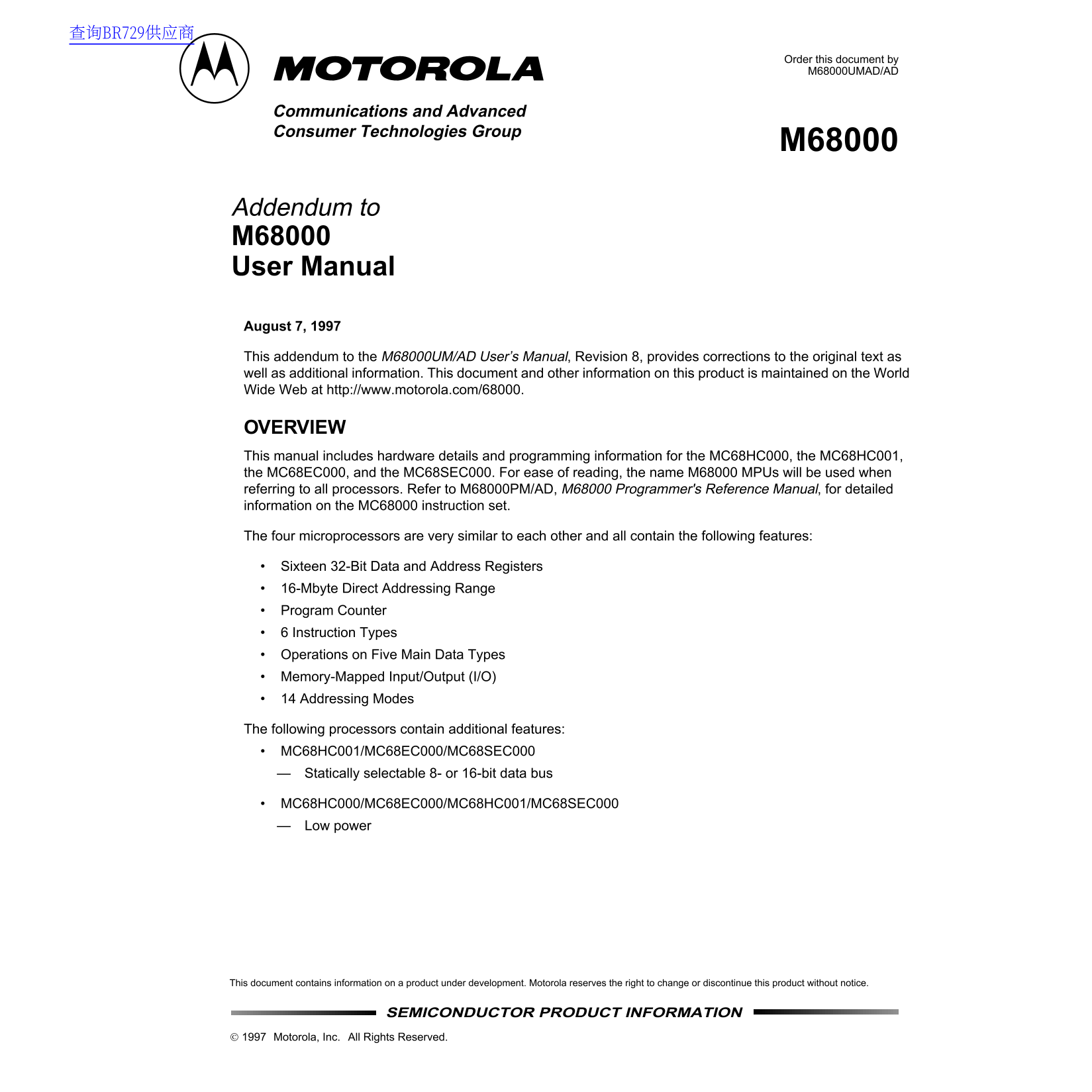
Order this document by M68000UMAD/AD

Communications and Advanced Consumer Technologies Group

Addendum to M68000 User Manual

August 7, 1997

This addendum to the M68000UM/AD User’s Manual , Revision 8, provides corrections to the original text as well as additional information. This document and other information on this product is maintained on the World Wide Web at http://www.motorola.com/68000.

OVERVIEW This manual includes hardware details and programming information for the MC68HC000, the MC68HC001, the MC68EC000, and the MC68SEC000. For ease of reading, the name M68000 MPUs will be used when referring to all processors. Refer to M68000PM/AD, M68000 Programmer's Reference Manual , for detailed information on the MC68000 instruction set.

The four microprocessors are very similar to each other and all contain the following features:

Sixteen 32-Bit Data and Address Registers 16-Mbyte Direct Addressing Range Program Counter 6 Instruction Types Operations on Five Main Data Types Memory-Mapped Input/Output (I/O) 14 Addressing Modes

The following processors contain additional features: MC68HC001/MC68EC000/MC68SEC000

Statically selectable 8- or 16-bit data bus

MC68HC000/MC68EC000/MC68HC001/MC68SEC000 Low power

This document contains information on a product under development. Motorola reserves the right to change or discontinue this product without notice.

SEMICONDUCTOR PRODUCT INFORMATION

Motorola, Inc. All Rights Reserved.

Page Summary Contents For Motorola Semiconductor MC6800 User's Guide and Manual

Page 1 查询BR729供应商 Order this document by M68000UMAD/AD Communications and Advanced Consumer Technologies Group Addendum to M68000 User Manual August 7, 1997 This addendum to the M68000UM/AD User’s Manual , R...
Page 2 The primary features of the MC68SEC000 embedded processor include the following: Direct Replacement for the MC68EC000 Pin-for-pin compatibility with the MC68EC000 in the plastic QFP and TQFP packages ...
Page 3 1.3 MC68SEC000 The MC68SEC000 is a cost-effective static embedded processor engineered for low-power applications. In addition to providing the substantial cost and performance benefits of the MC68EC0...
Page 4 2.0 SIGNAL DESCRIPTION Change Figure 3-3 on Page 3-2. VCC A23-A0 ADDRESS BUS D15-D0 DATA BUS PROCESSOR FC1 ASYNCHRONOUS STATUS BUS CONTROL DTACK MC68SEC000 BUS ARBITRATION BG CONTROL RESET SYSTEM INTE...
Page 5 power consumption to its quiescent value while maintaining the internal state of the processor. The low-power mode described below will be routinely tested as part of the MC68SEC000 test vectors provi...
Page 6 8-bit mode requires two bus cycles to fetch the immediate data of the STOP instruction. After the processor clock is disabled, it is often necessary to disable the clock to other sections of your circ...
Page 7 After the previous steps are completed, the MC68SEC000 will remain in the low-power mode until it recognizes the appropriate interrupt . External logic will also have to poll IPLB2–IPLB0 to detect the...
Page 8 An example trap routine is as follows: TRAP_x MOVE.B #0,$low_power_address /* Write that causes ADDRESS_MATCH to assert */ STOP #$2000 /* STOP instruction with desired interrupt mask */ RTE /* Return ...
Page 9 4.0 MC68SEC000 AC ELECTRICAL SPECIFICATIONS Replace Figure 10-2 on page 10-6 with Figure 7. DRIVE TO 2.4 V DRIVE TO 0.5 V VALID VALID OUTPUTS(1) CLK OUTPUT OUTPUT VALID VALID OUTPUTS(2) CLK OUTPUT n+1...
Page 10 5.0 MC68SEC000 DC ELECTRICAL SPECIFICATIONS Add the following table to Section 10.13 on page 10-23. (V = 5.0 Vdc 5%, 3.3 Vdc 10%,; GND = 0 Vdc; T = T to T CC CHARACTERISTIC SYMBOL MIN MAX MIN MAX UNIT...
Page 11 6.0 MC68SEC000 AC ELECTRICAL SPECIFICATIONS — CLOCK TIMING (See Figure 2) Add the following table and Figure 8 to Section 10.9 on page 10-9. 10MHz 16MHz 20MHz NUM. CHARACTERISTIC SYMBOL MIN MAX min ma...
Page 12 7.0 MC68SEC000 AC ELECTRICAL SPECIFICATIONS — READ AND WRITE CYCLES Add the following table and Figures 9 and 10 to Section 10.16. Applies to 3.3V and 5V. (GND = 0 V; T = T to T ; see Figures 3 and 4)...
Page 13 AC ELECTRICAL SPECIFICATIONS — READ AND WRITE CYCLES (Continued) 10MHz 16MHz 20MHz NUM CHARACTERISTIC UNIT MIN MAX MIN MAX MIN MAX AS, LDS, UDS Negated to Data-In Invalid (Hold Time on Read) ns 29A AS...
Page 14 FC2–FC0 LDS / UDS DTACK DATA IN BERR / BR (NOTE 2) HALT / RESET ASYNCHRONOUS INPUTS (NOTE 1) NOTES: 1. Setup time for the asynchronous inputs IPL2–IPL0 and AVEC (#47) guarantees their recognition at t...
Page 15 FC2–FC0 LDS / UDS 14A20A DTACK DATA OUT BERR / BR (NOTE 2) HALT / RESET ASYNCHRONOUS INPUTS (NOTE 1) NOTES: 1. Timing measurements are referenced to and from a low voltage of 0.8 V and a high voltage ...
Page 16 8.0 MC68SEC000 AC ELECTRICAL SPECIFICATIONS — BUS ARBITRATION Add the following table and Figure 11 to Section 10.17. (GND = 0 Vdc; T = T to T ; refer to Figure 13) 10MHz 16MHz 20MHz NUM CHARACTERISTI...
Page 17 STROBES AND R/W NOTE: Setup time to the clock (#47) for the asynchronous inputs BERR, BR, DTACK, IPL2-IPL0, and VPA guarantees their recognition at the next falling edge of the clock. Figure 11. Bus A...
Page 18 FC2-FC0 NOTES: Waveform measurements for all inputs and outputs are specified at: logic high 2.0 V, logic low = 0.8 V. This diagram also applies to the 68EC000. Figure 13. Bus Arbitration Timing—Idle ...
Page 19 FC2-FC0 NOTE: Waveform measurements for all inputs and outputs are specified at: logic high 2.0 V, logic low = 0.8 V. This diagram also applies to the 68EC000. Figure 14. Bus Arbitration Timing - Acti...
Page 20 FC2-FC0 NOTES: Waveform measurements for all inputs and outputs are specified at: logic high 2.0 V, logic low = 0.8 V. This diagram also applies to the 68EC000. Figure 15. Bus Arbitration - Multiple B...
Page 21 9.0 MECHANICAL DATA 9.1 PIN ASSIGNMENTS Add Figure 12 to Section 11.1. The following defines the pin assignment and the package dimensions of the 64 lead QFP (FU package) and 64 lead TQFP (PB package)...
Page 22 10.0 PACKAGE DIMENSIONS - FU SUFFIX This diagram replaces the one on Page 11-16 64 Lead Quad Flat Pack Case 840B-01 MILLIMETERS INCHES MIN MAX MIN MAX 16.95 17.45 0.667 0.687 13.90 14.10 0.547 0.555 1...
Page 23 11.0 PACKAGE DIMENSIONS - PB SUFFIX Add the following to Section 11.2. 64 Lead Thin Quad Flat Pack Case 840F-02 MILLIMETERS INCHES MIN MAX MIN MAX 12.00 BSC 0.472 BSC A1 6.00 BSC 0.236 BSC 10.00 BSC 0...
Page 24 12.0 PACKAGE/FREQUENCY AVAILABILITY Replaces Section 11.1 The following tables identify the packages and operating frequencies available for the MC68HC000, MC68HC001, MC68EC000, and the MC68SEC000. MC...
Page 25 ORDERING INFORMATION Add the following to Section 11. The following tables contains the ordering information for the MC68SEC000. MC68SEC000 Ordering Information TEMPERATURE PACKAGE BODY SIZE LEAD SPAC...
Page 26 Motorola reserves the right to make changes without further notice to any products herein. Motorola makes no warranty, representation or guarantee regarding the suitability of its products for any par...

Manual Details

Brand Motorola
Pages 26
File Size 113.33 KB
Published July 15, 2026
1 views

Enter the captcha to get the download link:

captcha

Frequently Asked Questions

Is the MC68SEC000 a direct replacement for the MC68EC000?

Yes, it provides pin-for-pin compatibility in both plastic QFP and TQFP packages.

Does the processor support low-power operation?

The MC68SEC000 consumes a typical 0.5mA current in static standby mode at 3.3V.

Can code written for M68000 family members be migrated easily?

Yes, object-code is fully upward compatible with other M68000 Family products and higher performance members.

What addresses are available to the processor?

It offers a sixteen 32-Bit Data and Address Registers and a 16-Mbyte Direct Addressing Range.