Motorola MC74AC564 MC74ACT564 Data Handbook
Summary
This high-speed octal D-Type Latch (MC74AC564/74ACT564) is an edge-triggered digital component featuring eight independent D inputs and low-power 3-state outputs, making it perfect for bus-oriented systems. It functions as a versatile input or output port ideal for microprocessors requiring reliable clocking and enabling controls. The comprehensive manual provides essential electrical specifications, detailed functional descriptions, operational guidelines, and wiring diagrams required by electronics engineers to ensure precise system integration and stable performance in data storage applications.
Page 1 Text Content
OCTAL D-TYPE LATCH WITH 3-STATE OUTPUTS
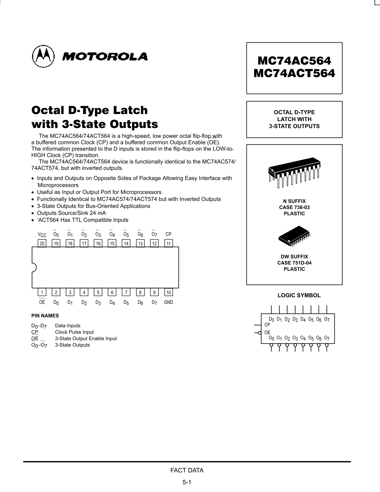
The MC74AC564/74ACT564 is a high-speed, low power octal flip-flop with a buffered common Clock (CP) and a buffered common Output Enable (OE). The information presented to the D inputs is stored in the flip-flops on the LOW-to- HIGH Clock (CP) transition. The MC74AC564/74ACT564 device is functionally identical to the MC74AC574/ 74ACT574, but with inverted outputs. Inputs and Outputs on Opposite Sides of Package Allowing Easy Interface with Microprocessors Useful as Input or Output Port for Microprocessors Functionally Identical to MC74AC574/74ACT574 but with Inverted Outputs
N SUFFIX
3-State Outputs for Bus-Oriented Applications CASE 738-03 Outputs Source/Sink 24 m A PLASTIC ′ACT564 Has TTL Compatible Inputs
VCC O0 O1 O2 O3 O4 O5 O6 O7 CP
DW SUFFIX CASE 751D-04 PLASTIC
LOGIC SYMBOL
OE D0 D1 D2 D3 D4 D5 D6 D7 GND
PIN NAMES
D0 D1 D2 D3 D4 D5 D6 D7 D0–D7 Data Inputs CP
CP Clock Pulse Input OE
OE 3-State Output Enable Input O0 O1 O2 O3 O4 O5 O6 O7
O0–O7 3-State Outputs
FACT DATA 5-1
Page Summary Contents For Motorola MC74AC564 MC74ACT564 Data Handbook
Manual Details
| Brand | Motorola |
|---|---|
| Pages | 8 |
| File Size | 195.26 KB |
| Published | July 22, 2026 |
Enter the captcha to get the download link:

Frequently Asked Questions
How is data loaded into the flip-flops?
The information presented to the D inputs is stored during the LOW-to-HIGH Clock (CP) transition.
Under what condition are the outputs readable?
The eight flip-flops’ contents are available at the outputs when the Output Enable (OE) input is LOW.
What is the recommended operating voltage range for this device?
The typical supply voltage 'Vcc' ranges from 2.0 V to 5.0 V.
How does the MC74AC564 compare to the MC74AC574?
It is functionally identical but features inverted outputs.