Motorola MC74AC157 MC74ACT157 Data Handbook
Summary
Elevate your digital signal processing with this high-speed quad 2-input multiplexer (MUX). Engineered for precise data routing, this module selects four distinct bits from two diverse sources using dedicated control inputs. This manual serves as a comprehensive technical guide for electronics engineers and hardware designers, detailing the functional architecture, logic diagrams, truth tables, and detailed electrical characteristics. It provides all necessary information—including operating conditions, maximum ratings, and performance metrics—for reliable integration into complex digital circuits and function generator designs.
Page 1 Text Content
查询MC74AC157供应商
QUAD 2-INPUT MULTIPLEXER
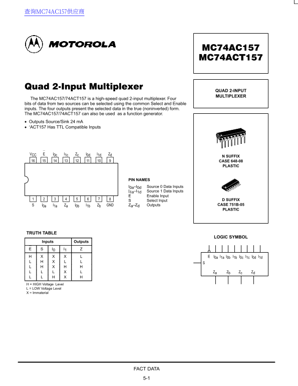
The MC74AC157/74ACT157 is a high-speed quad 2-input multiplexer. Four bits of data from two sources can be selected using the common Select and Enable inputs. The four outputs present the selected data in the true (noninverted) form. The MC74AC157/74ACT157 can also be used as a function generator. Outputs Source/Sink 24 m A ′ACT157 Has TTL Compatible Inputs
VCC I0c I1c Zc I0d I1d Zd
N SUFFIX CASE 648-08 PLASTIC
PIN NAMES I0a–I0d Source 0 Data Inputs I1a–I1d Source 1 Data Inputs
Enable Input
Select Input D SUFFIX I0a I1a Za I0b I1b Zb GND Za–Zd Outputs CASE 751B-05 PLASTIC
TRUTH TABLE
LOGIC SYMBOL
Inputs Outputs I0 I1
Za Zb Zc Zd
H = HIGH Voltage Level L = LOW Voltage Level X = Immaterial
FACT DATA 5-1
Page Summary Contents For Motorola MC74AC157 MC74ACT157 Data Handbook
Manual Details
| Brand | Motorola |
|---|---|
| Pages | 6 |
| File Size | 167.37 KB |
| Published | May 30, 2026 |
Enter the captcha to get the download link:

Frequently Asked Questions
What is the primary function of the MC74AC157?
It is a high-speed quad 2-input multiplexer, allowing selection of four data bits from two sources using Select and Enable inputs.
How does the device operate regarding logic control?
When E (Enable) is HIGH, the outputs are determined by the state of the Select input (S). The output equation is Z = E•(I •S+I •S).
What power range should be used for general use?
The DC Supply Voltage (VCC) must be between -0.5 to +7.0 V. However, Recommended Operating Conditions suggest a typical supply voltage of 5.0 V.
If the device is used as a function generator, what does it implement?
It implements logic for a 4-pole, 2-position switch, capable of generating any four of sixteen different switches based on two variable inputs (Select input).