# A B C D E F G H I J K L M N O P Q R S T U V W X Y Z

MAXIM MAX105 Dual 6-Bit 800Msps ADC with On-Chip Wideband Input Amplifier

Summary

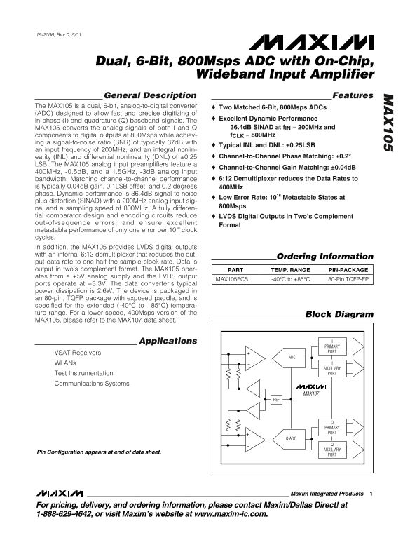
Experience ultra-high-speed signal processing with the MAX105, a dual, 6-Bit, 800 Msps Analog-to-Digital Converter (ADC). Optimized for digitizing I/Q baseband signals, it features integrated wideband amplifiers and superior dynamic performance. This comprehensive manual provides system engineers and designers with all necessary technical details—including electrical specifications, pin mapping, and operational guidelines—for integrating the MAX105 into demanding applications such as VSAT receivers, WLAN systems, or advanced test instrumentation in communications.
📄 Preview PAGE OF 21

Page 1 Text Content

19-2006; Rev 0; 5/01

Dual, 6-Bit, 800Msps ADC with On-Chip,

Wideband Input Amplifier

General Description Features

The MAX105 is a dual, 6-bit, analog-to-digital converter Two Matched 6-Bit, 800Msps ADCs (ADC) designed to allow fast and precise digitizing of

Excellent Dynamic Performance

in-phase (I) and quadrature (Q) baseband signals. The

MAX105 converts the analog signals of both I and Q 36.4d B SINAD at f IN 200MHz and

components to digital outputs at 800Msps while achiev- f CLK 800MHz

ing a signal-to-noise ratio (SNR) of typically 37d B with

Typical INL and DNL: ±0.25LSB

an input frequency of 200MHz, and an integral nonlin-

earity (INL) and differential nonlinearity (DNL) of ±0.25 Channel-to-Channel Phase Matching: ±0.2°

LSB. The MAX105 analog input preamplifiers feature a

Channel-to-Channel Gain Matching: ±0.04d B

400MHz, -0.5d B, and a 1.5GHz, -3d B analog input

bandwidth. Matching channel-to-channel performance 6:12 Demultiplexer reduces the Data Rates to

is typically 0.04d B gain, 0.1LSB offset, and 0.2 degrees 400MHz phase. Dynamic performance is 36.4d B signal-to-noise

Low Error Rate: 1016 Metastable States at

plus distortion (SINAD) with a 200MHz analog input sig-

800Msps

nal and a sampling speed of 800MHz. A fully differen- tial comparator design and encoding circuits reduce LVDS Digital Outputs in Two’s Complement out-of-sequence errors, and ensure excellent

Format

metastable performance of only one error per 1016 clock cycles. In addition, the MAX105 provides LVDS digital outputs with an internal 6:12 demultiplexer that reduces the out-

Ordering Information

put data rate to one-half the sample clock rate. Data is output in two’s complement format. The MAX105 oper- PART TEMP. RANGE PIN-PACKAGE ates from a +5V analog supply and the LVDS output

MAX105ECS -40°C to +85°C 80-Pin TQFP-EP

ports operate at +3.3V. The data converter’s typical power dissipation is 2.6W. The device is packaged in an 80-pin, TQFP package with exposed paddle, and is specified for the extended (-40°C to +85°C) tempera- ture range. For a lower-speed, 400Msps version of the

Block Diagram

MAX105, please refer to the MAX107 data sheet.

Applications

PRIMARY PORT

VSAT Receivers

I ADC

WLANs

AUXILIARY Test Instrumentation PORT

Communications Systems

MAX107

PRIMARY PORT

Q ADC

AUXILIARY

Pin Configuration appears at end of data sheet.

Maxim Integrated Products

For pricing, delivery, and ordering information, please contact Maxim/Dallas Direct! at 1-888-629-4642, or visit Maxim’s website at www.maxim-ic.com.

Page Summary Contents For MAXIM MAX105 Dual 6-Bit 800Msps ADC with On-Chip Wideband Input Amplifier

Page 1 19-2006; Rev 0; 5/01 Dual, 6-Bit, 800Msps ADC with On-Chip, Wideband Input Amplifier General Description Features The MAX105 is a dual, 6-bit, analog-to-digital converter Two Matched 6-Bit, 800Msps AD...
Page 2 Dual, 6-Bit, 800Msps ADC with On-Chip, Wideband Input Amplifier ABSOLUTE MAXIMUM RATINGS AVCC, AVCCI, AVCCQ and AVCCR to AGND............-0.3V to +6V Differential Voltage Between CLK+ and CLK- ..........
Page 3 Dual, 6-Bit, 800Msps ADC with On-Chip, Wideband Input Amplifier ELECTRICAL CHARACTERISTICS (continued) (AVCC = AVCCI = AVCCQ = AVCCR = +5V, OVCCI = OVCCQ = +3.3V, AGND = AGNDI = AGNDQ = AGNDR = 0, OGN...
Page 4 Dual, 6-Bit, 800Msps ADC with On-Chip, Wideband Input Amplifier ELECTRICAL CHARACTERISTICS (continued) (AVCC = AVCCI = AVCCQ = AVCCR = +5V, OVCCI = OVCCQ = +3.3V, AGND = AGNDI = AGNDQ = AGNDR = 0, OGN...
Page 5 Dual, 6-Bit, 800Msps ADC with On-Chip, Wideband Input Amplifier ELECTRICAL CHARACTERISTICS (continued) (AVCC = AVCCI = AVCCQ = AVCCR = +5V, OVCCI = OVCCQ = +3.3V, AGND = AGNDI = AGNDQ = AGNDR = 0, OGN...
Page 6 AM PL IT UD (d B) AM PL IT UD (d FS AM PL IT UD (d FS Dual, 6-Bit, 800Msps ADC with On-Chip, Wideband Input Amplifier Typical Operating Characteristics (AVCC = AVCCI = AVCCQ = AVCCR = +5V, OVCCI = OVC...
Page 7 TH (d B) SF DR (d B) SN (d B) Dual, 6-Bit, 800Msps ADC with On-Chip, Wideband Input Amplifier Typical Operating Characteristics (continued) (AVCC = AVCCI = AVCCQ = AVCCR = +5V, OVCCI = OVCCQ = +3.3V, ...
Page 8 RE FE RE NC VO LT AG (V SF DR (d B) AM PL IT UD (d B) Dual, 6-Bit, 800Msps ADC with On-Chip, Wideband Input Amplifier Typical Operating Characteristics (continued) (AVCC = AVCCI = AVCCQ = AVCCR = +5V,...
Page 9 Dual, 6-Bit, 800Msps ADC with On-Chip, Wideband Input Amplifier Pin Description PIN NAME FUNCTION 1, 20 T.P. Test Point. Do not connect. REF Reference Output Analog Reference Supply. Supply voltage fo...
Page 10 Dual, 6-Bit, 800Msps ADC with On-Chip, Wideband Input Amplifier Pin Description (continued) PIN NAME FUNCTION A3Q+ Auxiliary Output Data Bit 3, Q-Channel A3Q- Complementary Auxiliary Output Data Bit 3...
Page 11 Dual, 6-Bit, 800Msps ADC with On-Chip, Wideband Input Amplifier Pin Description (continued) PIN NAME FUNCTION P2I+ Primary Output Data Bit 2, I-Channel A2I- Complementary Auxiliary Output Data Bit 2, ...
Page 12 Dual, 6-Bit, 800Msps ADC with On-Chip, Wideband Input Amplifier DREADY+/DREADY- PRIMARY P0I+/P0I- MAX105 DATA PORT I ADC AUXILIARY A0I+/A0I- PRE-AMP DATA PORT INI- REF CM BUFFER REFERENCE DOR 10kΩ 2kΩ...
Page 13 Dual, 6-Bit, 800Msps ADC with On-Chip, Wideband Input Amplifier Table 1. Digital Output Codes Corresponding to a DC-Coupled Single-Ended Analog Input IN-PHASE INPUTS INVERTED INPUTS OUT-OF-RANGE BIT O...
Page 14 Dual, 6-Bit, 800Msps ADC with On-Chip, Wideband Input Amplifier tude) to +10d Bm (2VP-P clock signal amplitude). The MAX105 dynamic performance specifications are determined by a single-ended clock dr...
Page 15 Dual, 6-Bit, 800Msps ADC with On-Chip, Wideband Input Amplifier ADC SAMPLE MAX105 ADCs SAMPLE ON THE RISING EDGE OF CLK+ CLK- N+1 N+2 N+3 N+4 N+5 N+6 N+7 N+8 N+9 N+10 N+11 N+12 N+13 N+14 N+15 N+16 N+1...
Page 16 Dual, 6-Bit, 800Msps ADC with On-Chip, Wideband Input Amplifier DREADY+/DREADY- FROM PREVIOUS STAGE MAX2108 QUADRATURE PRIMARY DEMODULATOR DATA PORT P0I-P5I I ADC AUXILIARY PRE-AMPNYQUIST FILTER DATA ...
Page 17 Dual, 6-Bit, 800Msps ADC with On-Chip, Wideband Input Amplifier PC BOARD AVCC PC BOARD AGND FERRITE-BEAD SUPPRESSORS PC BOARD OVCC OVCCI, OVCCQ PC BOARD OGND AVCCRAVCCR OVCCI OVCCI AGNDR OGNDI AGNDR O...
Page 18 Dual, 6-Bit, 800Msps ADC with On-Chip, Wideband Input Amplifier 80-PIN TQFP PACKAGE WITH EXPOSED PAD BONDING WIRE EXPOXY THERMAL LAND COPPER PLANE, 1oz. EXPOSED PAD COPPER COPPER TRACE, 1oz. TRACE, 1o...
Page 19 Dual, 6-Bit, 800Msps ADC with On-Chip, Wideband Input Amplifier Total Harmonic Distortion (THD) CLK- THD is typically the ratio of the RMS sum of the first four CLK+ harmonics of the input signal to t...
Page 20 Dual, 6-Bit, 800Msps ADC with On-Chip, Wideband Input Amplifier Pin Configuration REF A1I- AVCCR P1I+ AGNDR P4 Q- P1I- P4 I- AGNDI OV A0I+ OV CC CC INI- OG ND A0I- OG ND INI+ A3 Q+ P01+ A3 I+ AGNDI A3...
Page 21 Dual, 6-Bit, 800Msps ADC with On-Chip, Wideband Input Amplifier Package Information Maxim cannot assume responsibility for use of any circuitry other than circuitry entirely embodied in a Maxim produc...

Manual Details

Brand Dual
Pages 21
File Size 669.67 KB
Published May 20, 2026
209 views

Enter the captcha to get the download link:

captcha

Frequently Asked Questions

What is the measured dynamic performance of the ADC at 200MHz?

The device features a SINAD of 36.4dB when processing an analog input signal at 200MHz.

How does the MAX105 handle and output its digital data?

It includes an internal 6:12 demultiplexer that reduces the data rate, which is then output in two's complement format.

What voltage levels are required for the analog inputs versus the LVDS outputs?

The input preamplifiers require a +5V analog supply, while the LVDS digital ports operate at +3.3V.