LINEAR Signal Chain Noise Analysis for RF-to-Digital Receivers Design Note 439 Cheng-Wei Pei
Summary
Optimize your RF-to-Digital receiver design with comprehensive guidance on signal chain noise analysis. This manual details expert methodologies for calculating overall system sensitivity by accurately tracking and combining noise characteristics across complex cascaded stages, including RF front ends, IF/baseband amplifiers, and ADCs. Essential for radio and signal system designers who must ensure optimal performance and component selection regardless of changing impedance or noise units (NF vs. SNR).
Page 1 Text Content
Signal Chain Noise Analysis for RF-to-Digital Receivers Design Note 439 Cheng-Wei Pei
Introduction equal to an NF of approximately 14d B), so here we use NF. Designers of signal receiver systems often need to per- When working in a fi xed-impedance (50Ω) environment, form cascaded chain analysis of system performance using NF simplifi es the analysis of an RF signal chain. However, if the assumptions of constant impedance and
from the antenna all the way to the ADC. Noise is a criti-
proper source/load termination are not valid, then NF
cal parameter in the chain analysis because it limits the
calculations become less straightforward.
overall sensitivity of the receiver. An application’s noise requirement has a signifi cant infl uence on the system IF/baseband components, such as amplifi ers, are typically topology, since the choice of topology strives to optimize specifi ed with noise spectral density, which is commonly the overall signal-to-noise ratio, dynamic range and measured in volts and amps per square-root Hertz (n V/√Hz several other parameters. One problem in noise calcula- and p A/√Hz). The contribution of current noise (p A/√Hz) tions is translating between the various units used by the is usually negligible in low impedance environments. ADC components in the chain: namely the RF, IF/baseband, noise is primarily specifi ed as a signal-to-noise ratio
and digital (ADC) sections of the circuit. (SNR) in decibels. SNR is the ratio of the maximum input signal to the total integrated input noise of the ADC. In
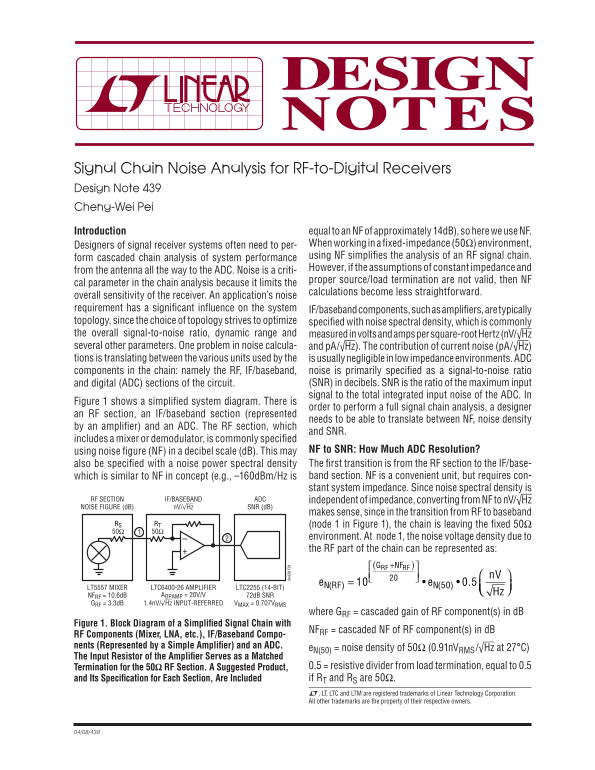
Figure 1 shows a simplifi ed system diagram. There is
order to perform a full signal chain analysis, a designer
an RF section, an IF/baseband section (represented
needs to be able to translate between NF, noise density
by an amplifi er) and an ADC. The RF section, which
and SNR.
includes a mixer or demodulator, is commonly specifi ed
using noise fi gure (NF) in a decibel scale (d B). This may NF to SNR: How Much ADC Resolution? also be specifi ed with a noise power spectral density The fi rst transition is from the RF section to the IF/base- which is similar to NF in concept (e.g., –160d Bm/Hz is band section. NF is a convenient unit, but requires con- stant system impedance. Since noise spectral density is
RF SECTION IF/BASEBAND ADC independent of impedance, converting from NF to n V/√Hz NOISE FIGURE (d B) n V/ Hz SNR (d B)
makes sense, since in the transition from RF to baseband
RS RT (node 1 in Figure 1), the chain is leaving the fi xed 50Ω 50Ω 50Ω
environment. At node 1, the noise voltage density due to the RF part of the chain can be represented as:
NFRF )⎡ RF
LT5557 MIXER LTC6400-26 AMPLIFIER LTC2255 (14-BIT) RF )•
⎝⎜ Hz ⎠⎟
NFRF = 10.6d B AOPAMP = 20V/V 72d B SNR GRF = 3.3d B 1.4n V/ Hz INPUT-REFERRED VMAX = 0.707VRMS
where GRF = cascaded gain of RF component(s) in d B
Figure 1. Block Diagram of a Simplifi ed Signal Chain with
NFRF = cascaded NF of RF component(s) in d B
RF Components (Mixer, LNA, etc.), IF/Baseband Compo- nents (Represented by a Simple Amplifi er) and an ADC.
e N(50) = noise density of 50Ω (0.91n VRMS/√Hz at 27°C)
The Input Resistor of the Amplifi er Serves as a Matched
Termination for the 50Ω RF Section. A Suggested Product, 0.5 = resistive divider from load termination, equal to 0.5 and Its Specifi cation for Each Section, Are Included if RT and RS are 50Ω. L, LT, LTC and LTM are registered trademarks of Linear Technology Corporation. All other trademarks are the property of their respective owners.
Page Summary Contents For LINEAR Signal Chain Noise Analysis for RF-to-Digital Receivers Design Note 439 Cheng-Wei Pei
Manual Details
| Brand | Linear |
|---|---|
| Pages | 2 |
| File Size | 83.41 KB |
| Published | May 30, 2026 |
Enter the captcha to get the download link:
