LINEAR A Low Power, Direct-to-Digital IF Receiver with Variable Gain Design Note 482 Walter Stroiffer
Summary
This document details a high-performance Variable Gain Amplifier plus ADC (VGA + ADC) IF Receiver designed for direct-to-digital signal processing in modern wireless communications. It provides robust demodulation of Intermediate Frequency (IF) signals, enabling the single-step digitization of both I and Q information while maintaining an exceptional dynamic range over a wide gain adjust setting. Ideal for RF engineers developing base station receivers or advanced test equipment handling complex standards like WCDMA and beyond.
Page 1 Text Content
A Low Power, Direct-to-Digital IF Receiver with Variable Gain Design Note 482 Walter Strifl er Introduction
TYPICAL 16384 POINT FFT 4-CHANNEL WCDMA CCDF
–10 Modern communication receivers require an ADC to 4-CHANNEL WCMDA SIGNAL AT –20 –12.5d BFSRMS TO ADC INPUT
digitize an incoming analog signal for decoding in a –30 MIN ADC CODE = 1030
MAX ADC CODE = 15438
suitable FPGA device. The direct-conversion method of –40
receiver design typically performs a single frequency
downconversion and an analog-to-digital conversion 0.001
(ADC) near baseband. While elegant and simple, this PO ER EN SI TY (d BF S/ 3H z) –80 PEAK-TO-AVERAGE RATIO (d B)
receiver architecture has problems with in-band block- –90 –109 VGA+ADC
–63d Bc ACPR
–100 NOISE FLOOR
ers, out-of-band interferers and LO leakage refl ections
within the receiver itself. –111.6 ADC NOISE FLOOR
In the face of these problems, basestation receivers FREQUENCY (MHz) DN4WS F01 often require a robust solution that is achieved using
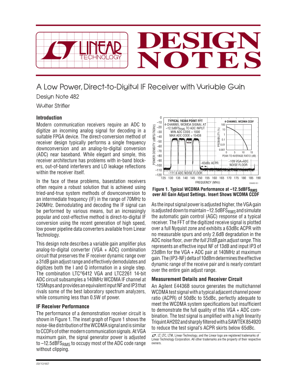
Figure 1. Typical WCDMA Performance at –12.5d BFSRMS
tried-and-true system methods of downconversion to
over All Gain Adjust Settings. Insert Shows WCDMA CCDF
an intermediate frequency (IF) in the range of 70MHz to
240MHz. Demodulating and decoding the IF signal can As the input signal power is adjusted higher, the VGA gain be performed by various means, but an increasingly is adjusted down to maintain –12.5d BFSRMS and simulate popular and cost-effective method is direct-to-digital IF the automatic gain control (AGC) response of a typical
PR OB AB IL IT
conversion using the recent generation of high speed, receiver. The FFT of the digitized receive signal is plotted low power pipeline data converters available from Linear over a full Nyquist zone and exhibits a 63d Bc ACPR with Technology. no measurable spurs and only 2.6d B degradation in the ADC noise fl oor, over the full 31d B gain adjust range. This
This design note describes a variable gain amplifi er plus
represents an effective input NF of 13d B and input IP3 of
analog-to-digital converter (VGA + ADC) combination
23d Bm for the VGA + ADC pair at 140MHz at maximum
circuit that preserves the IF receiver dynamic range over
gain. The (IP3-NF) delta of 10d Bm determines the effective
a 31d B gain adjust range and effectively demodulates and
dynamic range of the receive pair and is nearly constant
digitizes both the I and Q information in a single step.
over the entire gain adjust range.
The combination LTC®6412 VGA and LTC2261 14-bit
ADC circuit subsamples a 140MHz WCDMA IF channel at Measurement Details and Receiver Circuit
125Msps and provides an equivalent input NF and IP3 that An Agilent E4436B source generates the multichannel rivals some of the best laboratory spectrum analyzers, WCDMA test signal with a typical adjacent channel power while consuming less than 0.5W of power. ratio (ACPR) of 50d Bc to 55d Bc, perfectly adequate to
meet the WCDMA system specifi cations but insuffi cient
IF Receiver Performance
to demonstrate the full quality of this VGA + ADC com-
The performance of a demonstration receiver circuit is
bination. The test signal is amplifi ed with a high linearity
shown in Figure 1. The inset graph of Figure 1 shows the
Triquint AH202 and sharply fi ltered with a SAWTEK 854920
noise-like distribution of the WCDMA signal and is similar
to reduce the test signal’s ACPR skirts below 65d Bc.
to CCDFs of other modern communication signals. At VGA
L, LT, LTC, LTM, Linear Technology, and the Linear logo are registered trademarks of
maximum gain, the signal generator power is adjusted
Linear Technology Corporation. All other trademarks are the property of their respective to –12.5d BFSRMS to occupy most of the ADC code range owners.
without clipping.
Page Summary Contents For LINEAR A Low Power, Direct-to-Digital IF Receiver with Variable Gain Design Note 482 Walter Stroiffer
Manual Details
| Brand | Linear |
|---|---|
| Pages | 2 |
| File Size | 85.25 KB |
| Published | June 18, 2026 |
Enter the captcha to get the download link:

Frequently Asked Questions
What is the frequency range this receiver circuit best handles?
The system simulates a 140MHz WCDMA IF channel at 240MHz peak operating frequency.
How does the Variable Gain Amplifier (VGA) help maintain system performance?
The VGA provides an adjustable gain of up to 31dB, ensuring the receiver maintains its dynamic range and minimizes signal degradation across different input power levels.
What key specifications are achieved with this LTC6412/LTC2261 pair?
This combination achieves a low effective input Noise Figure (NF) of 13dB and an Input IP3 of 23dBm at maximum gain, while maintaining an ACPR of 63dBc.
Why is this indirect-to-digital method preferred for IF receivers?
It offers superior dynamic range control and eliminates the in-band block-spacers, out-of-band interferers, and LO leakage reflections associated with traditional direct-conversion methods.