LINEAR Fast TDD Transmission Using an Upconverting Mixer with a High Side Switch – Design Note 480
Summary
This manual provides detailed technical instructions for implementing a high-performance High Side Voltage (V) switch in TDD and Burst Mode transmitter applications. It covers the optimal use of the LT5579 upconverting mixer to dramatically improve fast power on/off switching capabilities, achieving turn-on times under 1μs. Ideal for RF engineers and designers building advanced wireless communication infrastructure that requires quick signal modulation adjustments.
Page 1 Text Content
Fast Time Division Duplex (TDD) Transmission Using an Upconverting Mixer with a High Side Switch – Design Note 480 Vladimir Dvorkin
Introduction adding an external high side power supply switch (note Many wireless infrastructure time division duplex (TDD) that this technique is equally effective for the lower fre- transmit applications require fast on/off switching of the quency upconverting mixer, LT5578).
transmitter, typically within one to fi ve microseconds.
High Side VCC Switch for a Burst Mode Transmitter
There are several different ways to implement fast Tx
Using the LT5579 Mixer
on/off switching, including the use of RF switches in the
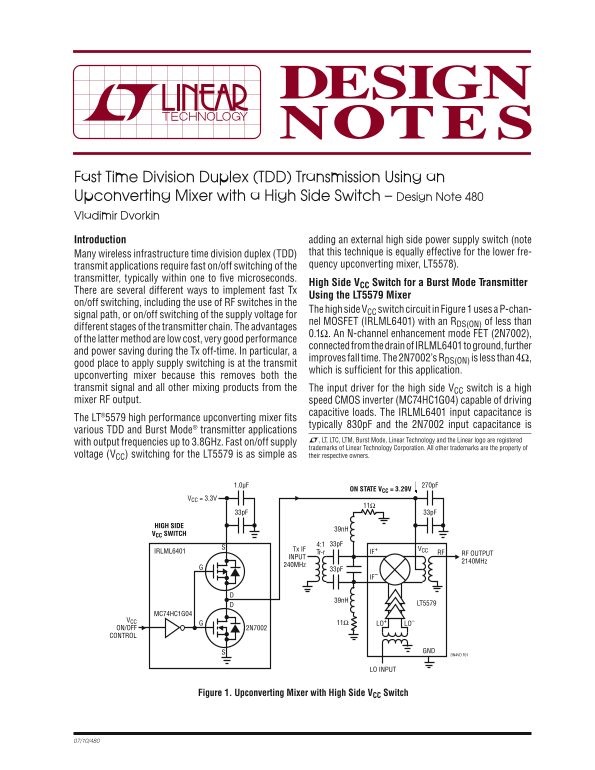
The high side VCC switch circuit in Figure 1 uses a P-chan-
signal path, or on/off switching of the supply voltage for
nel MOSFET (IRLML6401) with an RDS(ON) of less than
different stages of the transmitter chain. The advantages
0.1Ω. An N-channel enhancement mode FET (2N7002),
of the latter method are low cost, very good performance
connected from the drain of IRLML6401 to ground, further
and power saving during the Tx off-time. In particular, a
improves fall time. The 2N7002’s RDS(ON) is less than 4Ω,
good place to apply supply switching is at the transmit
which is suffi cient for this application.
upconverting mixer because this removes both the transmit signal and all other mixing products from the The input driver for the high side VCC switch is a high mixer RF output. speed CMOS inverter (MC74HC1G04) capable of driving
capacitive loads. The IRLML6401 input capacitance is
The LT®5579 high performance upconverting mixer fi ts
typically 830p F and the 2N7002 input capacitance is
various TDD and Burst Mode® transmitter applications
L, LT, LTC, LTM, Burst Mode, Linear Technology and the Linear logo are registered
with output frequencies up to 3.8GHz. Fast on/off supply
trademarks of Linear Technology Corporation. All other trademarks are the property of
voltage (VCC) switching for the LT5579 is as simple as their respective owners.
1.0μF 270p FON STATE VCC = 3.29V
VCC = 3.3V
HIGH SIDE
VCC SWITCH
Tx IF
IRLML6401 Tr-r IF+ RFVCC
RF OUTPUT
INPUT
2140MHz
240MHz
LT5579
MC74HC1G04
GVCC 11Ω LO+ LO–
ON/OFF 2N7002 CONTROL
DN4VD F01
LO INPUT
Figure 1. Upconverting Mixer with High Side VCC Switch
Page Summary Contents For LINEAR Fast TDD Transmission Using an Upconverting Mixer with a High Side Switch – Design Note 480
Manual Details
| Brand | Linear |
|---|---|
| Pages | 2 |
| File Size | 97.45 KB |
| Published | May 29, 2026 |
Enter the captcha to get the download link:

Frequently Asked Questions
How fast is the turn-on and turn-off time for the high side V switch?
The total turn-on time is 650ns, and the total turn-off time is 500ns.
What components are used in the recommended high side V switch setup?
It uses three primary parts: an IRLML6401, a 2N7002, and an MC74HC1G04 CMOS inverter.
What is advised for the LO injection VCO output when performing TDD applications?
Use a buffered output to prevent pulling and ensure better reverse isolation between the on and off states.