LINEAR Wideband RF ICs for Power Detection and Control – Design Note 335 by James Wong and Vladimir Dvorkin Owner's Manual User Guide
Summary
These specialized wideband RF Integrated Circuits are essential for accurate power detection, monitoring, and control in advanced wireless systems. This manual provides detailed technical solutions for designers integrating these ICs into mobile phones, Wi-Fi infrastructure, RFID readers, and other high-frequency communication devices. It covers system-level architectures—including impedance matching and signal demodulation circuits—ensuring optimal performance and adherence to regulatory standards across various frequency ranges (300MHz up to 12GHz).
Page 1 Text Content
advertisement
Wideband RF ICs for Power Detection and Control – Design Note 335 James Wong and Vladimir Dvorkin
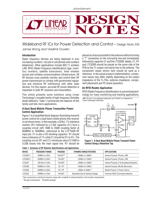
Introduction placed as close as possible to the antenna without forming Radio frequency devices are being deployed in ever a “T” connection on the microstrip line and immediately followed by capacitor C1 and the LTC5509. Ideally, C1, R1
increasing numbers, not just in cell phones and cordless
and LTC5509 should be placed on the same side of the
telephones. Other applications include 802.11 wireless
LAN, RFID (Radio Frequency Identification) tags, inven- PCB as the Tx output microstrip line to the antenna. The component values shown here should be used as a
tory monitors, satellite transceivers, fixed wireless
reference. In the actual product implementation, compo-
access and wireless communications infrastructure. All
RF devices must carefully monitor and control their RF nent values may differ slightly depending on the output impedance of the Tx PAs, antenna impedance, compo-
power transmission to comply with government regula-
nent placement and PC board parasitics.
tion and minimize RF interference with other radio devices. For this reason, accurate RF power detection is
An RFID Reader Application
important in both RF receivers and transmitters.
RFID (Radio Frequency Identification) is a promising tech- This article presents some solutions using Linear nology for many monitoring and tracking applications,
Technology’s versatile family of high frequency Schottky ,LTC and LT are registered trademarks and Thin SOT is a trademark of
Linear Technology Corporation.
diode detectors. Table 1 summarizes the features of this
family and lists more applications. C1
ANTENNAR1
A Dual-Band Mobile Phone Transmitter Power
Control Application Tx PA MODULE CELL BAND
Figure 1 is a simplified block diagram illustrating transmit
LTC5509 DIPLEXER power control for a dual band mobile phone (the receiver SHDN RFIN is not shown here). In this example, a 324Ω, 1% tolerance GND GND resistor (R1) followed by a 2.2p F capacitor (C1) form a VOUT VCC PCS BAND
Li-Ion0.1µF
coupling circuit with 18d B to 20d B coupling factor at 850MHz to 1850MHz, referenced to the LTC®5509 RF input pin. C1 is also a DC blocking capacitor. R1 should
MOBILE PHONE BB/DSP VPC
DN335 F01
have a tolerance of 1% while C1 should be 2% to 5%. The coupling circuit (R1 and C1) introduces about 0.15d B to Figure 1. A Dual Band Mobile Phone Transmit Power
0.2d B losses into the main signal line. R1 should be Control Using a Resistive Tap
Table␣ 1. Summary of RF Detector Specifications and Applications DEVICE FREQUENCY RANGE PACKAGE DYNAMIC RANGE/FEATURES APPLICATIONS
LTC5505-1 300MHz to 3GHz Thin SOTTM –28d Bm to 18d Bm* General Purpose, Phones, ISM
LTC5505-2 300MHz to 3GHz Thin SOT –32d Bm to 12d Bm* General Purpose, Phones, ISM
LTC5507 100 KHz to 1GHz Thin SOT –34d Bm to 14d Bm* General Purpose LF & Broadband Detection
LTC5508 300MHz to 7GHz SC–70† –32d Bm to 12d Bm* General Purpose, WLAN, Microwave
LTC5509 300MHz to 3GHz SC–70† –30d Bm to 6d Bm** Mobile Phones Tx Power Control
LTC5532 300MHz to 7GHz Thin SOT Adjustable Gain & Starting Voltage Precision RSSI & Envelope Detection
*Gain compression extends the dynamic range with a tradeoff of reduced linearity in the transfer characteristic. **No gain compression. †Smallest package.
Page Summary Contents For LINEAR Wideband RF ICs for Power Detection and Control – Design Note 335 by James Wong and Vladimir Dvorkin Owner's Manual User Guide
Manual Details
| Brand | Linear |
|---|---|
| Pages | 2 |
| File Size | 103.89 KB |
| Published | June 19, 2026 |
Enter the captcha to get the download link:

Frequently Asked Questions
What is the optimal frequency range for the LTC5532 detector?
It offers useable performance from 300MHz to 7GHz, but can reliably detect data over a much wider working range.
How should I choose component values for the coupling circuit (R1 and C1)?
R1 requires a 1% tolerance, while C1 needs to be between 2% and 5%.
What hardware is crucial for ensuring accurate RF power detection in transmitters?
It is necessary to carefully monitor and control the RF impedance of the Tx PAs and antenna impedance.
How can I enhance the selectivity of an RFID reader receiver circuit?
Using a lowpass or bandpass filter at the detector output provides additional receiver selectivity for demodulation.