LINEAR True RMS Converter – Autoranging Design Note 339 by Philip Karantzalis and Jim Mahoney
Summary
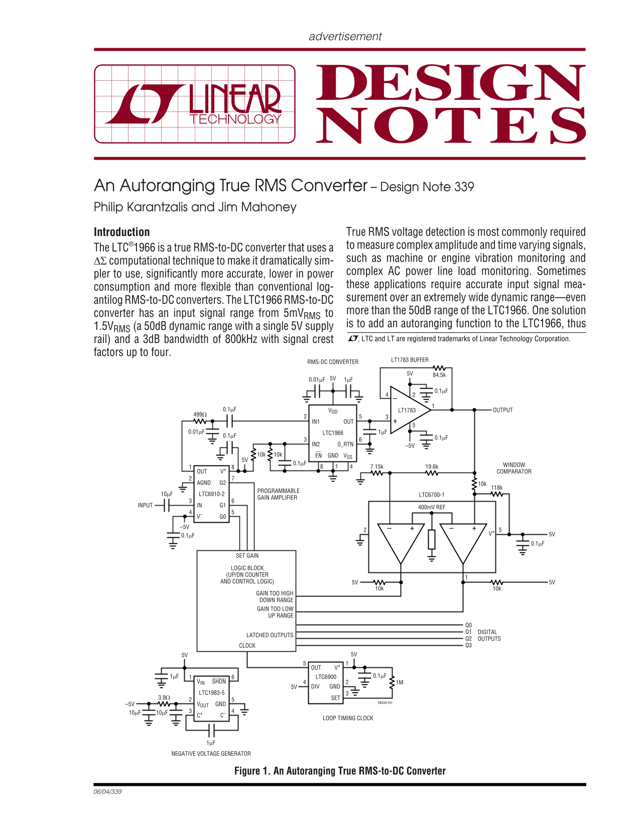
Measure complex AC power signals accurately using this Autoranging True RMS-to-DC Converter solution. Designed for demanding applications like vibration monitoring and load analysis, it measures time-varying inputs across an extended 80dB dynamic range. This manual details the robust architecture, including automatic gain adjustments across linear, over, and under range modes. It is essential technical documentation for electrical engineers and designers building precision signal measurement equipment.
Page 1 Text Content
advertisement
An Autoranging True RMS Converter – Design Note 339 Philip Karantzalis and Jim Mahoney
Introduction True RMS voltage detection is most commonly required to measure complex amplitude and time varying signals,
The LTC®1966 is a true RMS-to-DC converter that uses a
such as machine or engine vibration monitoring and
∆Σ computational technique to make it dramatically sim-
complex AC power line load monitoring. Sometimes
pler to use, significantly more accurate, lower in power
consumption and more flexible than conventional log- these applications require accurate input signal mea- +– surement over an extremely wide dynamic range—even
antilog RMS-to-DC converters. The LTC1966 RMS-to-DC
more than the 50d B range of the LTC1966. One solution
converter has an input signal range from 5m VRMS to
is to add an autoranging function to the LTC1966, thus
1.5VRMS (a 50d B dynamic range with a single 5V supply
rail) and a 3d B bandwidth of 800k Hz with signal crest , LTC and LT are registered trademarks of Linear Technology Corporation.
factors up to four.
RMS-DC CONVERTER LT1783 BUFFER
0.1µF VDD LT1783 OUTPUT
IN1 OUT
0.01µF LTC1966 1µF
IN2 0_RTN –5V
10k10k VSSGNDEN
0.1µF WINDOW
OUT V+1 COMPARATOR
AGND G2 10k
PROGRAMMABLE
10µF LTC6910-2 LTC6700-1
GAIN AMPLIFIER
ININPUT G1 400m V REF
SET GAIN
LOGIC BLOCK (UP/DN COUNTER AND CONTROL LOGIC) 5V 5V
GAIN TOO HIGH DOWN RANGE GAIN TOO LOW UP RANGE
Q0 Q1 DIGITAL
LATCHED OUTPUTS
Q2 OUTPUTS CLOCK Q3
OUT V+5
1µF LTC6900 0.1µF
VIN SHDN 1M
5V DIV GND
LTC1983-5
3.9Ω SET
DN339 F01
–5V VOUT GND
LOOP TIMING CLOCK
NEGATIVE VOLTAGE GENERATOR
Figure 1. An Autoranging True RMS-to-DC Converter
Page Summary Contents For LINEAR True RMS Converter – Autoranging Design Note 339 by Philip Karantzalis and Jim Mahoney
Manual Details
| Brand | Linear |
|---|---|
| Pages | 2 |
| File Size | 99.69 KB |
| Published | June 22, 2026 |
Enter the captcha to get the download link:

Frequently Asked Questions
What maximum dynamic range can this converter achieve?
The autorranging loop expands the input signal range up to 80dB.
What types of signals are best suited for monitoring with this circuit?
It is used for measuring complex AC power lines and time-varying signals, like engine vibration.
Must the system use multiple voltage supplies to operate?
No, the entire circuit can be biased from a single 5V supply.