LINEAR RS232 Quick User Guide
Summary
The RS232 standard provides a reliable, general-purpose electrical interface for robust serial data communication. This quick guide serves as an essential technical reference for building or troubleshooting point-to-point modem links across various connection standards (DB9, DB25). It covers detailed signaling specifications, including voltage requirements, signal pinouts, and signal timing diagrams. Furthermore, the manual provides a comprehensive list of compatible RS232 transceiver part numbers, allowing professionals and engineers to select the optimal components for high-speed and reliable serial system design.
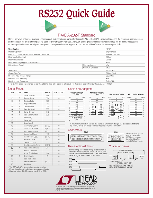
Page 1 Text Content
RS232 Quick Guide
TIA/EIA-232-F Standard
RS232 conveys data over a simple unterminated, multiconductor cable at rates up to 20k B. The RS232 standard specifies the electrical characteristics and connector for an all encompassing point-to-point modem interface. Although the original specification was intended for modems, subsequent renderings shed unneeded signals to expand its scope and use as a general purpose serial interface at data rates up to 1MB.
Specification RS232 Mode of Operation Single-Ended Number of Drivers and Receivers Allowed on One Line 1 Driver, 1 Receiver Maximum Cable Length 50 Feet* Maximum Data Rate 20k B/s Maximum Voltage Applied to Driver Output ±25V Driver Output Signal Minimum Loaded ±5V
Maximum Unloaded ±15V
Termination 3kΩ to 7kΩ Output Slew Rate 30V/µs (Max) Receiver Input Voltage Range ±25V Max Receiver Input Sensitivity ±3V Receiver Input Resistance 3kΩ to 7kΩ * For 2500p F cable capacitance, as per IEA 232D for data rates less than 20k baud. For data rates greater than 20k baud, CLOAD = 1000p F.
Signal Pinout Cable and Adapters DB25 DB9 Name ABBR. DTE ⇔ DCE Straight Through Minimum Straight
Cable Cable Null Modem Cable AT to 25-Pin Adapter
Frame Ground FG
DTE DCE DTE DCE DTE DCE 25-PIN 9-PIN
Transmit Data TD FG TD FG TD
Receive Data RD TD RD SG RD RD SG TD TD RTS
Request to Send RTS
RTS RTS RTS RD RD CTS
Clear to Send CTS
CTS CTS CTS RTS RTS DSR Data Set Ready DSR DSR DSR DSR CTS CTS SG SG DCD DCD DSR DTR DCD
Signal Ground SG
DTR DTRDCD DCD DTR
Data Carrier Detect DCD
TC (SYNC. ONLY) DTR DSR RI
(Reserved) RC (SYNC. ONLY) DCD
(Reserved) DTR
Unassigned
A minimum null modem cable is the same as a minimum straight cable except that RD and Sec. Carrier Detect (S) CD TD (Pins 2 and 3) are cross-connected as in the null modem cable.
Sec. Clear to Send (S) CTS
Connectors
Sec. Transmit Data (S) TD
DB25 DB9
Views are from the pin
Transmitter Clock TC
side of the female
Sec. Receive Data (S) RD (DCE) connector or
the wire side of the
Receiver Clock RC
male (DTE) connector.
Local Loopback Sec. Request to Send (S) RTS
Character Frame Relative Signal Timing
Data Terminal Ready DTR
Normal timing sequences during establishment of
Remote Loopback CHARACTER FRAME
communications are shown below. On half-duplex
DATA BIT
Signal Quality Detect SQ circuits, RTS is dropped as soon as the data is sent.
This is to signal a turnaround of the circuit.
Ring Indicator RI START STOP
BIT • • • MSB PAR BITLSB
Data Rate Select DTR
Transmitter Clock (E) TC DSR OTHER DATA BITS
OPTIONAL PARITY BIT
Test Mode RTS
MSB = MOST SIGNIFICANT DATA BIT
n The DTE ⇔ DCE column indicates data direction. CTS LSB = LEAST SIGNIFICANT DATA BIT n Pin numbers in bold indicate commonly used signals.
n Data rate select (Pin 23) can be from DTE or DCE.
L, LT, LTC, LTM, Linear Technology and the Linear logo are registered trademarks of Linear Technology Corporation. All other trademarks are the property of their respective owners.
Page Summary Contents For LINEAR RS232 Quick User Guide
Manual Details
| Brand | Linear |
|---|---|
| Pages | 2 |
| File Size | 440.66 KB |
| Published | June 16, 2026 |
Enter the captcha to get the download link:

Frequently Asked Questions
What is the maximum data rate supported by the RS232 standard?
The original specification was for modems, but subsequent rendrings expanded its scope to general purpose serial interface at data rates up to 1MB.
What are the specifications for a straight-through cable (DTE $\Leftrightarrow$ DCE)?
It connects Transmit Data (TD) $\Rightarrow$ FG and Receive Data (RD) $\Leftarrow$ FG, based on Pin 2 and Pin 3 respectively.
Which pins connect Signal Ground (SG)?
Signal Ground (SG) is connected via Pins 7 and 8 in the main connector diagram.