LINEAR LT3663 User Guide
Summary
Optimize your power reliability with this specialized supercapacitor charger. Designed for large capacitance banks used in critical Power Ride-Through applications, such as solid state RAID or high-speed storage systems. This robust unit provides adjustable voltage and current limits, delivering the high charging current necessary to minimize recharge time during unplanned power loss. The comprehensive manual details advanced control methodologies, including circuit balancing techniques that manage unequal supercapacitor values and complex series charging requirements for optimal performance. Ideal for professional electrical engineers designing mission-critical backup power systems.
Page 1 Text Content
L DESIGN IDEAS
Supercapacitor Charger with Adjustable Output Voltage and Adjustable Charging Current Limit
by Jim Drew Introduction
For applications using larger value supercapacitors (tens to hundreds of VCAP
12V VIN VOUT
farads), a charger circuit with a rela-
LT3663 BUCK
tively high charging current is needed 50F
GND GND
to minimize the recharge time of the RUN
system. Supercapacitors are used as BIAS TOP RAIL +
GND CONTROL TOP ENA
energy hold up devices in applications
CIRCUIT
TOP CAP + TOP RAIL –
such as solid state RAID disks, where (FIGURE 3)
TOP CAP – BOT RAIL +
information stored in high speed vola- BOT CAP + BOT ENA
VIN VOUT BOT CAP – GND
tile memory must be transferred to
LT3663 BUCK
non-volatile flash memory when power 50F
GND GND GNDRUN GND
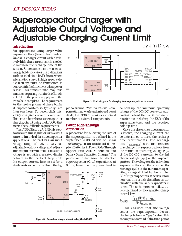
is lost. This transfer time may take minutes, requiring hundreds of farads to hold up the power supply until the transfer is complete. The requirement Figure 1. Block diagram for charging two supercapacitors in series for the recharge time of these banks of supercapacitors is typically less pin to ground. With its internal com- be held up, the minimum operating than one hour. To accomplish this, pensation network and internal boost voltage of the DC/DC converter sup- a high charging current is required. diode, the LT3663 requires a minimal porting the load, the distributed circuit This article describes a supercapacitor number of external components. resistances including the ESR of the charging circuit using the LT3663 that supercapacitors, and the required
meets these difficult requirements. Power Ride-Through hold up time. The LT3663 is a 1.2A, 1.5MHz step- Application Once the size of the supercapacitor
down switching regulator with output A procedure for selecting the size of is known, the charging current can current limit ideal for supercapacitor the supercapacitor is outlined in the be determined to meet the recharge applications. The part has an input September 2008 edition of Linear time requirements. The recharge voltage range of 7.5V to 36V,has Technology, in an article titled “Re- time (TRECHARGE) is the time required adjustable output voltage and adjust- place Batteries in Power Ride-Through to recharge the supercapacitors from able output current limit. The output Applications with Supercaps and the minimum operating voltage (VUV) voltage is set with a resistor divider 3mm × 3mm Capacitor Charger.” The of the DC/DC converter to the full network in the feedback loop while procedure determines the effective charge voltage (VFC) of the superca- the output current limit is set by a supercapacitor (CEFF) capacitance at pacitors. The voltage on the individual single resistor connected from the ILIM 0.3Hz, based on the power level to supercapacitors at the start of the
recharge cycle is the minimum oper-
VINVIN VOUT VOUT ating voltage divided by the number
IR05H40CSPTR 47µF
50V 1.2A (N) of supercapacitors in series. From
LT3663
16V here on, this article describes an ap-
BOOST
ENA RUN plication with two supercapacitors in
0.1µF 16V series. The recharge current (ICHARGE)
SW RFB1
L1 200k is determined by the capacitor charge 3.3µH
ILIM ISENSE control law:
RILIM GND FB
28.7k EFF FC UV
DFLS240
TCHARGE RECHARGE
This assumes that the voltage
L1: TDK VLCF5020T-3R3N1R7-1 86.6k
across the supercapacitor doesn’t discharge below the VUV/N value. This
Figure 2. Capacitor charger circuit using the LT3663 assumption is valid if the time period
Linear Technology Magazine • June 2009
Page Summary Contents For LINEAR LT3663 User Guide
Manual Details
| Brand | Linear |
|---|---|
| Pages | 3 |
| File Size | 484.81 KB |
| Published | June 01, 2026 |
Enter the captcha to get the download link:
