LINEAR Application Note 59 - LT1300 and LT1301 Micropower DC-DC Converters User Manual by Dale Eagar and Steve Pietkiewicz
Summary
Optimize your battery-powered designs with the LT1300 and LT1301 Micropower DC/DC Converters. This resource provides critical application knowledge, demonstrating how these highly efficient converters enable compact, reliable power solutions for equipment operating on limited battery capacity. The manual covers detailed theory of operation, block diagrams, and multiple circuits—including LED drivers and voltage buffers—proving that high performance can fit into minimal PCB space. Ideal for electronics engineers designing portable or low-power instrumentation that requires maximum longevity from difficult-to-manage battery sources.
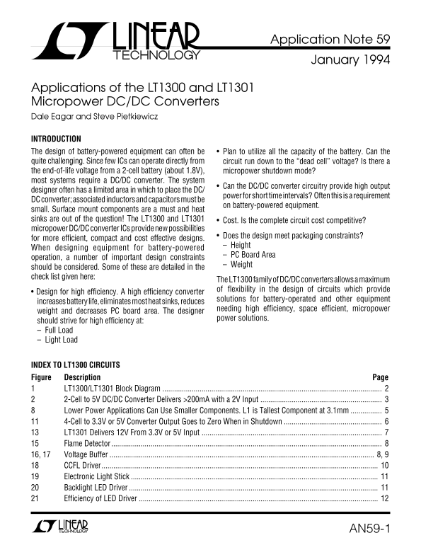
Page 1 Text Content
Application Note 59 January 1994
Applications of the LT1300 and LT1301 Micropower DC/DC Converters Dale Eagar and Steve Pietkiewicz
INTRODUCTION The design of battery-powered equipment can often be Plan to utilize all the capacity of the battery. Can the quite challenging. Since few ICs can operate directly from circuit run down to the “dead cell” voltage? Is there a the end-of-life voltage from a 2-cell battery (about 1.8V), micropower shutdown mode? most systems require a DC/DC converter. The system
Can the DC/DC converter circuitry provide high output
designer often has a limited area in which to place the DC/
power for short time intervals? Often this is a requirement
DC converter; associated inductors and capacitors must be
on battery-powered equipment.
small. Surface mount components are a must and heat sinks are out of the question! The LT1300 and LT1301 Cost. Is the complete circuit cost competitive? micropower DC/DC converter ICs provide new possibilities
Does the design meet packaging constraints?
for more efficient, compact and cost effective designs.
– Height
When designing equipment for battery-powered
– PC Board Area
operation, a number of important design constraints
– Weight
should be considered. Some of these are detailed in the check list given here:
The LT1300 family of DC/DC converters allows a maximum of flexibility in the design of circuits which provide
• Design for high efficiency. A high efficiency converter
solutions for battery-operated and other equipment
increases battery life, eliminates most heat sinks, reduces
needing high efficiency, space efficient, micropower
weight and decreases PC board area. The designer
power solutions.
should strive for high efficiency at: – Full Load – Light Load
INDEX TO LT1300 CIRCUITS Figure Description Page
LT1300/LT1301 Block Diagram 2-Cell to 5V DC/DC Converter Delivers >200m A with a 2V Input Lower Power Applications Can Use Smaller Components. L1 is Tallest Component at 3.1mm 4-Cell to 3.3V or 5V Converter Output Goes to Zero When in Shutdown LT1301 Delivers 12V From 3.3V or 5V Input Flame Detector
16, 17 Voltage Buffer 8, 9
CCFL Driver............................................................................................................................................. Electronic Light Stick Backlight LED Driver Efficiency of LED Driver
AN59-1
Page Summary Contents For LINEAR Application Note 59 - LT1300 and LT1301 Micropower DC-DC Converters User Manual by Dale Eagar and Steve Pietkiewicz
Manual Details
| Brand | Linear |
|---|---|
| Pages | 12 |
| File Size | 208.18 KB |
| Published | June 21, 2026 |
Enter the captcha to get the download link:

Frequently Asked Questions
What is the minimum input voltage for the LT1300 to operate efficiently?
The device operates across an input voltage range of 1.8V to 10V.
Which feature allows the LT1300 to maintain high efficiency during low power usage?
When enabled, the LT1300 runs in Burst Mode using the LM DC/DC CONVERTERS.
What is the approximate quiescent current draw of the A1 and A2 devices when idle?
The internal oscillator frequency setter consumes a typical current of 120μA for both A1 and A2.
How does the maximum efficiency relate to battery operation?
High overall efficiency (87%) is listed as a feature, which helps preserve full night vision in applications like flashlights.