# A B C D E F G H I J K L M N O P Q R S T U V W X Y Z

Hewlett-Packard HP DesignJet HD Professional Scanner HP Designjet HD Pro Scanner - Assembly Instructions

Summary

This comprehensive guide provides detailed instructions for assembling and setting up the HP Designjet HD Pro Scanner system, including mounting the Panel PC touch screen component. The manual covers everything from safe unpacking procedures to step-by-step stand assembly using a complete list of specialized hardware. Furthermore, it details essential routine maintenance tasks, such as cleaning the scanning area and performing necessary calibration, ensuring optimal operation for all users.
📄 Preview PAGE OF 17

Page 1 Text Content

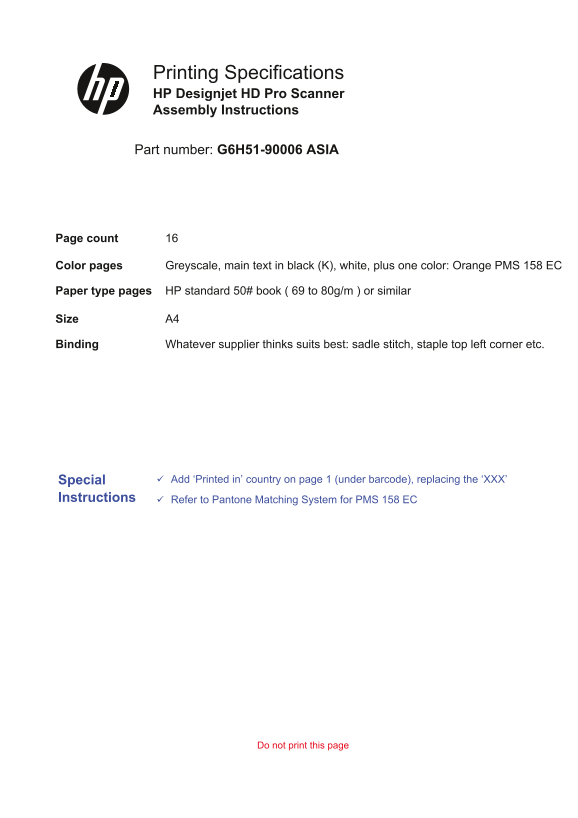
Printing Specifications HP Designjet HD Pro Scanner Assembly Instructions

Part number: G6H51-90006 ASIA

Page count

Color pages Greyscale, main text in black (K), white, plus one color: Orange PMS 158 EC

Paper type pages HP standard 50# book ( 69 to 80g/m ) or similar

Size A4

Binding Whatever supplier thinks suits best: sadle stitch, staple top left corner etc.

Special Add ‘Printed in’ country on page 1 (under barcode), replacing the ‘XXX’

Instructions Refer to Pantone Matching System for PMS 158 EC

Do not print this page

Page Summary Contents For Hewlett-Packard HP DesignJet HD Professional Scanner HP Designjet HD Pro Scanner - Assembly Instructions

Page 1 Printing Specifications HP Designjet HD Pro Scanner Assembly Instructions Part number: G6H51-90006 ASIA Page count Color pages Greyscale, main text in black (K), white, plus one color: Orange PMS 158 ...
Page 2 EN During the stand assembly you will see some reference to the HP Designjet EN following symbol labels which appear on some items, standing Read these instructions carefully... for left side, and rig...
Page 3 EN Box contents Assembly kit contents Box Description Quantity 1. Maintenance sheet supplied 2. Plastic dust cover 3. Scanner Screw M5 x 16 (Torx T25) for stand feet 4. Paper guides Screw M5 x 8 (Torx...
Page 4 ZHCN ZHTW 2. 塑料防尘盖 用于固定机架支脚的螺钉 M5 x 16 機架支腳螺絲 M5 × 16 (Torx T25) 3. 扫描仪 (Torx T25) 4. 纸张导板 4. 紙張導板 機架支腳螺絲 M5 × 8 (Torx T20) 用于固定机架的螺钉 M5 x 8 (Torx T20) 掃描器專用螺絲 (Torx T20) 用于固定扫描仪的特殊螺钉 (Torx T20) 5. 退纸...
Page 5 Fix the foot to the leg with 4 screws Fix the other foot to the other leg with 4 screws. Make sure the wheels are locked. Attach the cross bar to the legs using 4 screws. EN JA 4本のネジを使用して脚部に足部を固定します。 ...
Page 6 EN Slot the supports into the legs, and fix with 4 screws. Insert the basket struts (4) into the slots until they snap into Slot the basket into the basket struts. Place some packaging boxes, or somet...
Page 7 Lift the scanner into place locating the rubber feet in the Fix with the four special screws. With the protective foam in place, put the panel PC face Attach one end of the earth cable where shown, us...
Page 8 At this point you must decide on which side you are going to fit the panel PC assembly. This can be fitted on the left or right side of the stand. The next steps, explain how to fit the panel PC assem...
Page 9 If you want to lock the tilt position of the panel PC, remove Make sure the DC power adapter is placed in the tray Fit the adapter tray under the scanner support on the The unit is now assembled and s...
Page 10 EN 22You are now required to clean the scan area. To do so you will need the cleaning tools provided in the maintenance kit and a cleaning fluid (not included in the maintenance kit). Caution: do not ...
Page 11 Clean the white background plate with a lint-free cloth and a Clean the transport rollers and surrounding area. Dry the white background plate, rollers, and surrounding Close the scanner cover and pus...
Page 12 x 12 x Network** DC connector* Keep out dust and reduce maintenance time: when not in Insert the DC connector* and two network cables** into Insert the network cables into the panel PC and insert the ...
Page 13 Insert the power cable into the DC power adapter in the tray Connect the power cable to the scanner. Fit the cables into the clips. Then attach the clips to the Connect the power cables from the scann...
Page 14 You are now required to calibrate the scanner. For this you Switch on the scanner and leave it to warm up for some When the green (ready status) light has appeared, press the Note: When switching on t...
Page 15 Important: when setting up for the first time, make sure EN that the scanner is turned on for at least one hour before moving on to the next step of camera alignment calibra- tion. Slight light intens...
Page 16 Next, you should check the TCP/IP settings in your touch screen, and correct them if necessary. If you intend to scan to the net- work, with the HP Designjet scan software, files to be shared across t...
Page 17 To add an HP Designjet printer to the printer list in your scanner software, follow these steps: 1: On the touch screen go to the setup tab. EN 2: Press option button and select system. 3: Press the b...

Manual Details

Brand HP
Pages 17
File Size 3.22 MB
Published June 17, 2026
4 views

Enter the captcha to get the download link:

captcha

Frequently Asked Questions

How many people are needed to unpack or assemble this scanner?

Since the scanner is heavy, you may need two people to unpack it.

How often should routine maintenance be performed on the unit?

It is recommended to perform daily maintenance about once a month.

Where can the panel PC touch screen assembly be mounted on the stand?

The component can be mounted on either the right or the left side of the stand.

What steps are needed to add an HP Designjet printer to the scanner software?

Go to the touchscreen setup tab, press 'Option', select 'System', and then press the button for the desired printer.