Fairchild MBRP3010N Data Handbook - Schottky Barrier Rectifier
Summary
This robust Schottky Barrier Rectifier is engineered for demanding power applications, excelling in switched mode power supplies due to its low forward voltage drop and high switching speed. Designed with over-voltage protection capabilities, it ensures reliable performance in sensitive electrical systems. The accompanying manual provides comprehensive technical specifications, including absolute maximum ratings, thermal characteristics, and detailed graphs of surge current capability, making it the essential resource for power electronics engineers selecting components for robust, efficient power management.
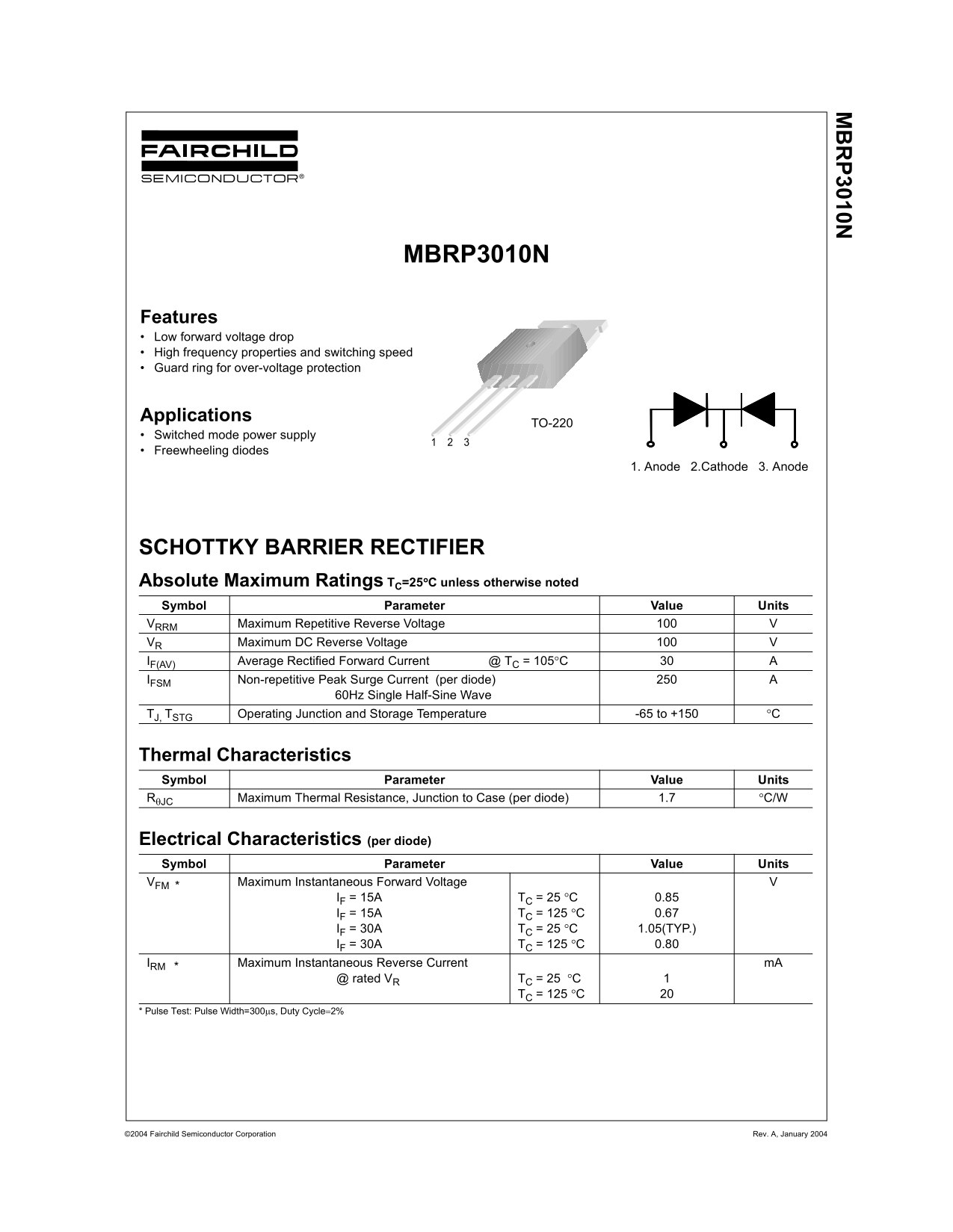
Page 1 Text Content
MBRP3010N
Features Low forward voltage drop High frequency properties and switching speed Guard ring for over-voltage protection
Applications
TO-220
Switched mode power supply
Freewheeling diodes
1. Anode 2.Cathode 3. Anode
SCHOTTKY BARRIER RECTIFIER Absolute Maximum Ratings TC=25°C unless otherwise noted Symbol Parameter Value Units VRRM Maximum Repetitive Reverse Voltage
VR Maximum DC Reverse Voltage
IF(AV) Average Rectified Forward Current @ TC = 105°C
IFSM Non-repetitive Peak Surge Current (per diode)
60Hz Single Half-Sine Wave
TJ, TSTG Operating Junction and Storage Temperature -65 to +150 °C
Thermal Characteristics Symbol Parameter Value Units RθJC Maximum Thermal Resistance, Junction to Case (per diode) 1.7 °C/W
Electrical Characteristics (per diode) Symbol Parameter Value Units VFM * Maximum Instantaneous Forward Voltage
IF = 15A TC = 25 °C 0.85
IF = 15A TC = 125 °C 0.67 IF = 30A TC = 25 °C 1.05(TYP.) IF = 30A TC = 125 °C 0.80
IRM * Maximum Instantaneous Reverse Current m A
@ rated VR TC = 25 °C
TC = 125 °C
* Pulse Test: Pulse Width=300µs, Duty Cycle=2%
©2004 Fairchild Semiconductor Corporation Rev. A, January 2004
Page Summary Contents For Fairchild MBRP3010N Data Handbook - Schottky Barrier Rectifier
Manual Details
| Brand | Fairchild |
|---|---|
| Pages | 4 |
| File Size | 46.99 KB |
| Published | July 06, 2026 |
Enter the captcha to get the download link:

Frequently Asked Questions
What is the absolute maximum average rectified forward current rating?
The maximum rating is 30 A at T = 105°C.
What is the maximum rated thermal resistance from junction to case?
The Maximum Thermal Resistance ($ heta_{JC}$) is 1.7 °C/W (per diode).
Is this device suitable for life support critical components?
No, its use as a critical component in life support devices requires express written approval from Fairchild Semiconductor Corporation.
In what package dimension format is this product supplied?
The physical dimensions provided are for the TO-220 package.