Fairchild FES16AT - FES16JT User Guide
Summary
Discover detailed specifications for a high-reliability series of semiconductor rectifiers, designed for robust power conversion applications. This manual provides comprehensive electrical characteristics, including absolute maximum ratings and thermal behavior, detailing performance variations across models like FEP16AT through FEP16JT. Essential for electrical engineers and hardware designers building reliable DC power supplies or industrial electronics needing high-power rectification components.
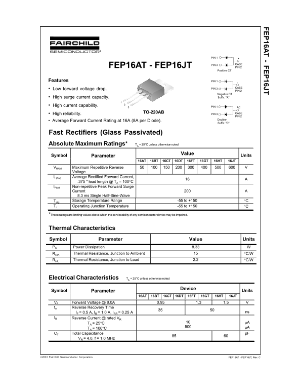
Page 1 Text Content
FEP16AT - FEP16JT
PIN 1
PIN 3 CASE
FEP16AT - FEP16JT PIN 2
Positive CT
Features PIN 1
PIN 3 CASE
Low forward voltage drop.
PIN 2
Negative CT High surge current capacity. Suffix "A"
High current capability. PIN 1
TO-220AB CASE
• High reliability. PIN 3
PIN 2
Doubler Suffix "D"
Fast Rectifiers (Glass Passivated) Absolute Maximum Ratings* TA = 25°C unless otherwise noted
Value
Symbol Parameter Units 16AT 16BT 16CT 16DT 16FT 16GT 16HT 16JT VRRM Maximum Repetitive Reverse 50 100 150 200 300 400 500 600 V
Voltage
IF(AV) Average Rectified Forward Current,
.375 " lead length @ TA = 100°C 16 A
IFSM Non-repetitive Peak Forward Surge
Current 8.3 ms Single Half-Sine-Wave
Tstg Storage Temperature Range -55 to +150 °C TJ Operating Junction Temperature -55 to +150 °C
*These ratings are limiting values above which the serviceability of any semiconductor device may be impaired.
Thermal Characteristics Symbol Parameter Value Units PD Power Dissipation 8.33 W RθJA Thermal Resistance, Junction to Ambient 15 °C/W RθJL Thermal Resistance, Junction to Lead 2.2 °C/W
Electrical Characteristics TA = 25°C unless otherwise noted
Device
Symbol Parameter Units 16AT 16BT 16CT 16DT 16FT 16GT 16HT 16JT VF Forward Voltage @ 8.0A 0.95 1.3 1.5 V trr Reverse Recovery Time
IF = 0.5 A, IR = 1.0 A, IRR = 0.25 A 35 50 ns
IR Reverse Current @ rated VR
TA = 25°C µA µA
TA = 100°C
CT Total Capacitance
VR = 4.0. f = 1.0 MHz
FEP16AT - FEP16JT, Rev. C2001 Fairchild Semiconductor Corporation
Page Summary Contents For Fairchild FES16AT - FES16JT User Guide
Manual Details
| Brand | Fairchild |
|---|---|
| Pages | 3 |
| File Size | 301.79 KB |
| Published | May 31, 2026 |
Enter the captcha to get the download link:

Frequently Asked Questions
What is the maximum repetitive reverse voltage rating (V RRM)?
The maximum RRM voltage varies by device, ranging from 50 V to 600 V.
What type of load are these components suitable for?
They can be used with both resistive and inductive loads.
How is power dissipation rated in Junction-to-Ambient (θJA)?
The thermal resistance (Rth) from junction to ambient (°C/W) is 15.
Does the device require special precautions for life support?
No. Fairchild's products are not authorized for use as critical components in life support devices or systems without explicit written approval.