# A B C D E F G H I J K L M N O P Q R S T U V W X Y Z

Fairchild FDP8880 FDB8880 User's Manual

Summary

The FDP8880 / FDB8880 is a high-performance N-Channel Power Trench MOSFET engineered to maximize the efficiency of DC/DC converters. Optimized for use with synchronous or conventional switching PWM controllers, it features extremely low on-resistance and fast switching capabilities. This comprehensive datasheet provides critical technical details, including detailed maximum operating ratings, dynamic electrical characteristics, thermal impedance curves, and full application guidelines. It is essential reference material for power electronics engineers designing high-current, reliable conversion systems.
📄 Preview PAGE OF 11

Page 1 Text Content

May 2008

FDP8880 / FDB8880 tm M

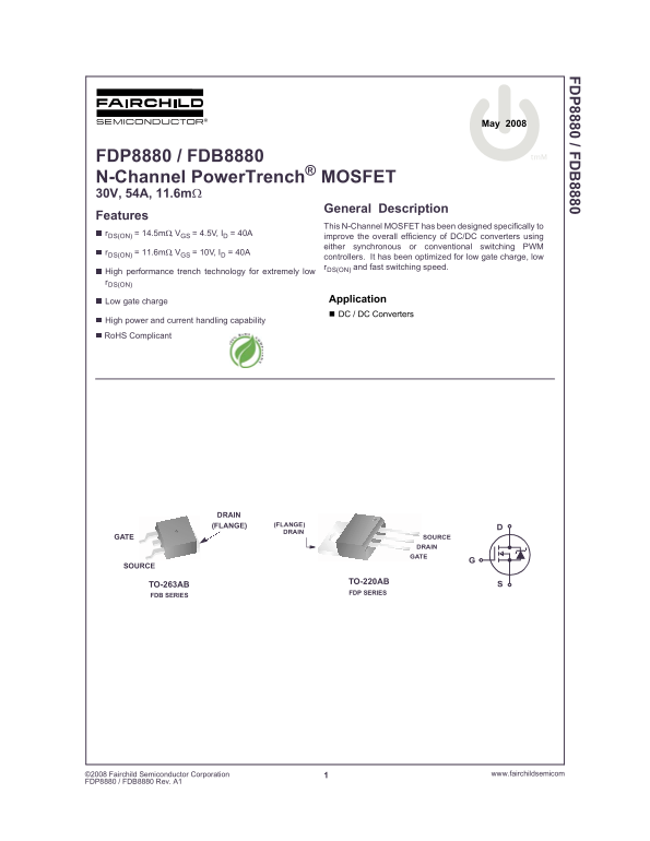
N-Channel Power Trench® MOSFET 30V, 54A, 11.6mΩ

General Description

Features

This N-Channel MOSFET has been designed specifically to

r DS(ON) = 14.5mΩ, VGS = 4.5V, ID = 40A

improve the overall efficiency of DC/DC converters using either synchronous or conventional switching PWM

r DS(ON) = 11.6mΩ, VGS = 10V, ID = 40A

controllers. It has been optimized for low gate charge, low r DS(ON) and fast switching speed.

High performance trench technology for extremely low r DS(ON)

Low gate charge Application DC / DC Converters

High power and current handling capability

Ro HS Complicant

DRAIN

(FLANGE) (FLANGE) DRAIN

GATE SOURCE DRAIN GATE

SOURCE

TO-220AB

TO-263AB

FDP SERIES

FDB SERIES

2008 Fairchild Semiconductor Corporation www.fairchildsemicom1

DP8880 / FDB8880 Rev. A1

Page Summary Contents For Fairchild FDP8880 FDB8880 User's Manual

Page 1 May 2008 FDP8880 / FDB8880 tm M N-Channel Power Trench® MOSFET 30V, 54A, 11.6mΩ General Description Features This N-Channel MOSFET has been designed specifically to r DS(ON) = 14.5mΩ, VGS = 4.5V, ID =...
Page 2 8880 / F MOSFET Maximum Ratings TC = 25°C unless otherwise noted Symbol Parameter Ratings Units VDSS Drain to Source Voltage VGS Gate to Source Voltage ±20 Drain Current AContinuous (TC = 25o C, VGS =...
Page 3 8880 / F Dynamic Characteristics CISS Input Capacitance p F VDS = 15V, VGS = 0V, COSS Output Capacitance p F f = 1MHz CRSS Reverse Transfer Capacitance p F RG Gate Resistance VGS = 0.5V, f = 1MHz - 2....
Page 4 8880 / F Typical Characteristics TC = 25°C unless otherwise noted , N IZ IS IP IO LT IP IE TC, CASE TEMPERATURE (o C) TC, CASE TEMPERATURE (o C) Figure 1. Normalized Power Dissipation vs Case Figure 2...
Page 5 8880 / F Typical Characteristics TC = 25°C unless otherwise noted (O IN , D IN , D IN IS TA Ω) If R = 0 t AV = (L)(IAS)/(1.3*RATED BVDSS - VDD) 10µs If R ≠ 0 t AV = (L/R)ln[(IAS*R)/(1.3*RATED BVDSS - ...
Page 6 8880 / F Typical Characteristics TC = 25°C unless otherwise noted , C PA IT IZ LT 1.5 1.1 ID = 250µA VGS = VDS, ID = 250µA TJ, JUNCTION TEMPERATURE (o C) TJ, JUNCTION TEMPERATURE (o C) Figure 11. Norm...
Page 7 Test Circuits and Waveforms BVDSS VARY t P TO OBTAIN IAS REQUIRED PEAK IAS RG 0V IAS 0.01Ω Figure 15. Unclamped Energy Test Circuit Figure 16. Unclamped Energy Waveforms VDD Qg(TOT) VDS VGS VGS = 10V ...
Page 8 8880 / F PSPICE Electrical Model .SUBCKT FDP8880 2 1 3 ; rev October 2004 Ca 12 8 9.5e-10 Cb 15 14 9.5e-10 LDRAIN Cin 6 8 1.15e-9 DPLCAP DRAIN Dbody 7 5 Dbody MOD RLDRAIN RSLC1 Dbreak 5 11 Dbreak MOD ...
Page 9 8880 / F SABER Electrical Model rev October 2004 template FDP8880 n2,n1,n3 electrical n2,n1,n3 var i iscl dp..model dbodymod = (isl=3e-12,ikf=10,nl=1.01,rs=5e-3,trs1=8e-4,trs2=2e-7,cjo=4.8e-10,m=0.55,...
Page 10 8880 / F PSPICE Thermal Model th JUNCTION REV 23 December 2003 FDP8880T CTHERM1 TH 6 8e-4 CTHERM2 6 5 1e-3 CTHERM3 5 4 2.5e-3 RTHERM1 CTHERM1 CTHERM4 4 3 2.6e-3 CTHERM5 3 2 8e-3 CTHERM6 2 TL 1.5e-2 RT...
Page 11 TRADEMARKS The following includes registered and unregistered trademarks and service marks, owned by Fairchild Semiconductor and/or its global subsidianries, and is not intended to be an exhaustive li...

Manual Details

Brand Fairchild
Pages 11
File Size 696.50 KB
Published May 31, 2026
49 views

Enter the captcha to get the download link:

captcha

Frequently Asked Questions

Are these components suitable for life support devices?

No, their use is not authorized for critical life support devices or systems without express written approval from Fairchild Semiconductor Corporation.

How do I account for increased temperature when calculating peak current?

You must derate the peak current using specific multipliers provided in the normalized charts if the ambient temperature exceeds 25°C.

What is the intended application for these N-Channel MOSFETs?

They are specifically designed to improve efficiency in DC/DC Converters utilizing synchronous or conventional switching PWM controllers.