Fairchild FCB20N60F User's Manual
Summary
The FCB20N60F SuperFET is a high-performance, low on-resistance 600V N-Channel FRFET designed for demanding power conversion applications. This manual provides comprehensive technical documentation, including detailed electrical characteristics, thermal data, and maximum ratings required for robust system design. It is essential reading for electrical engineers and power electronics designers building efficient AC/DC switching mode systems that require superior speed, minimal conduction loss, and high reliability in harsh environments.
Page 1 Text Content
December 2008
Super FET TM
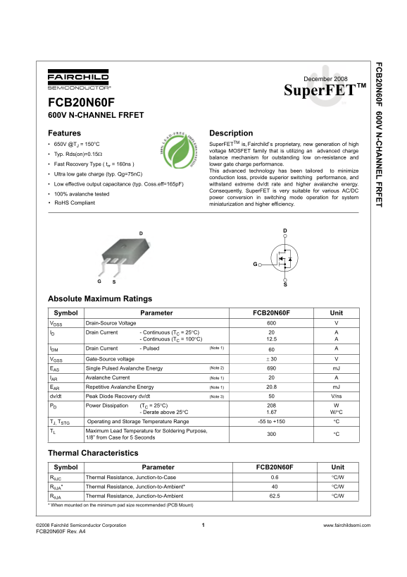
FCB20N60F 600V N-CHANNEL FRFET Features Description 650V @ TJ = 150°C Super FETTM is, s proprietary, new generation of high Fairchild'
voltage MOSFET family that is utilizing an advanced charge
Typ. Rds(on)=0.15
balance mechanism for outstanding low on-resistance and Fast Recovery Type ( trr = 160ns ) lower gate charge performance. This advanced technology has been tailored to minimize
Ultra low gate charge (typ. Qg=75n C)
conduction loss, provide superior switching performance, and Low effective output capacitance (typ. Coss.eff=165p F) withstand extreme dv/dt rate and higher avalanche energy. Consequently, Super FET is very suitable for various AC/DC
100% avalanche tested
power conversion in switching mode operation for system
Ro HS Compliant miniaturization and higher efficiency.
Absolute Maximum Ratings Symbol Parameter FCB20N60F Unit VDSS Drain-Source Voltage ID Drain Current - Continuous (TC = 25 C)
- Continuous (TC = 100 C) 12.5
IDM Drain Current - Pulsed (Note 1)
VGSS Gate-Source voltage
EAS Single Pulsed Avalanche Energy (Note 2) m J
IAR Avalanche Current (Note 1)
EAR Repetitive Avalanche Energy (Note 1) 20.8 m J
dv/dt Peak Diode Recovery dv/dt (Note 3) V/ns
PD Power Dissipation (TC = 25 C)
- Derate above 25 1.67 W/C
TJ, TSTG Operating and Storage Temperature Range -55 to +150 TL Maximum Lead Temperature for Soldering Purpose,
1/8” from Case for 5 Seconds
Thermal Characteristics Symbol Parameter FCB20N60F Unit
JC Thermal Resistance, Junction-to-Case 0.6 C/W
JA* Thermal Resistance, Junction-to-Ambient* C/W
JA Thermal Resistance, Junction-to-Ambient 62.5 C/W
* When mounted on the minimum pad size recommended (PCB Mount)
©200 Fairchild Semiconductor Corporation www.fairchildsemi.com FCB20N60F Rev. A
Page Summary Contents For Fairchild FCB20N60F User's Manual
Manual Details
| Brand | Fairchild |
|---|---|
| Pages | 8 |
| File Size | 1.13 MB |
| Published | May 20, 2026 |
Enter the captcha to get the download link:

Frequently Asked Questions
What drain-source voltage rating does the FCB20N60F support?
The maximum Drain-Source Voltage (DSS) is listed as 600 V.
What are the continuous and pulsed drain current ratings at different temperatures?
Continuous current is 20A at 25°C and 12.5A at 100°C; Pulsed current is up to 60A.
How does decreasing junction temperature affect the required dissipation area?
The thermal resistance (R T Junction-to-Ambient) changes from 40 °C/W at 25°C to a derated value above 25°C.
What are the key advantages of using this SuperFET technology?
It offers low on-resistance, superior switching performance, and ultra low gate charge for high efficiency in AC/DC power conversion.