Fairchild 6004 User's Manual
Summary
Optimize your designs with this comprehensive application note for Active PFC pre-regulator circuits using the FAN4810 controller. This guide provides electrical engineers and power supply designers with detailed, step-by-step theoretical calculations needed to select critical components. Learn how to meticulously calculate inductor values, optimize bulk capacitor sizing based on hold-up time requirements, and properly set gain modulator parameters for high-performance, efficient PFC converters compliant with IEC standards.
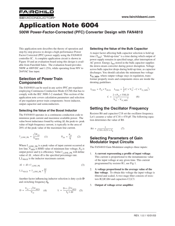
Page 1 Text Content
www.fairchildsemi.com
Application Note 6004 500W Power-Factor-Corrected (PFC) Converter Design with FAN4810
This application note describes the theory of operation and Selecting the Value of the Bulk Capacitor step-by-step process to design a high performance Power
A major factor affecting bulk capacitor selection is hold up
Factor Corrected (PFC) power supply using the FAN4810
time (T ). “Hold-up-time” is a time during which output of hld
controller IC. A complete application circuit is shown in
power supply remains in specified range, after interruption of
Figure 10 and an evaluation board using this design is avail-
AC power. Energy J stored in the bulk capacitor supplies thd
able from Fairchild Sales. The evaluation board provides
the down-steam converter during power disruption. Voltage
500W at 400VDC and 1.25A, while operating from 90V to
across bulk capacitor drops during hold-up time, as capacitor
264VAC line input.
discharges. You should calculate the minimum bus voltage , where output voltage stays in regulation, trans- O_MIN Selection of Power Train former properly resets and components stress are inside the Components derating guidelines.
The FAN4810 can be used in any active PFC pre-regulator 2× 2×(
JTHD PO THLD×= JTHD VO C– VO_MIN
employing Continuous Conduction Mode (CCM) that has to comply with the IEC 3000-3-2 standard. This section of the PO THLD××
application note covers calculation parameters and selection
VO VO_MIN
of pre-regulator power train components: boost inductor, output capacitor and semiconductors.
Setting the Oscillator Frequency
Selecting the Value of the Boost Inductor
Resistor R6 and capacitor C18 set the oscillator frequency.
The FAN4810 operates in a continuous conduction code to
Let’s assume a value of C18 = 470 p F. The following equa-
minimize peak current and maximize available power. The
tion determines the value of R6
value boost inductance found by setting I, the peak-to- peak value of high-frequency current, is typically in the area of 20% of the peak value of the maximum line current.
2PIN PO
I_LINE_PK (1) PIN (2)
VMIN Selecting Parameters of Gain
Modulator Input Circuits
Where I is a peak value of input current occurred at _LINE_PK
The FAN4810 Gain Modulator employs three inputs:
low line, V is RMS value of minimum line voltage, P is
output power and is efficiency. Value I will define
_LINE_PK
1. A current representing a profile of input voltage
value of I , where d I is the specified percentage rate.
This current is proportional to the instantaneous value
I_L is the inductor maximum current. MAX
of the input voltage at any given time. This current programmed by resistor R1, see Fig 1.
∆I d I I_LINE_PK×= (3)
∆I 2. A voltage proportional to the average value of the
I_LMAX I_LINE_PK
line voltage . To obtain this voltage the input voltage is filtered and scaled. A two-stage filter consists of resis-
Another factor influencing inductor selection is duty cycle tors R2,R3,R4 and capacitors C2,C3. and switching frequency
3. Output of voltage error amplifier
VO 2VMIN– 2VMIN×
VO f S ∆I×
REV. 1.0.1 10/31/03
Page Summary Contents For Fairchild 6004 User's Manual
Manual Details
| Brand | Fairchild |
|---|---|
| Pages | 10 |
| File Size | 534.32 KB |
| Published | June 01, 2026 |
Enter the captcha to get the download link:

Frequently Asked Questions
What is required for designing the bulk capacitor?
You must calculate the minimum bus voltage (V_O_MIN) to ensure output regulation, considering factors like hold-up time and available energy.
How does the FAN4810 operate in terms of electrical current?
It operates using Continuous Conduction Mode (CCM).
What parameters are used when selecting boost inductor components?
You must determine the oscillator frequency by setting resistors R6 and capacitor C18, which minimizes peak current and maximizes available power.
Is there a safety restriction for this product's use?
Fairchild warns that their products cannot be used as critical components in life support devices or systems without express written approval.