Fairchild FDC640P User Guide
Summary
Discover the FDC640P, a high-performance P-Channel MOSFET optimized for efficient power management solutions. Featuring low R DS(ON) and fast switching speed, this advanced component is engineered for critical applications including battery systems, load switches, and protection circuits. This datasheet provides complete technical specifications, outlining comprehensive electrical characteristics, thermal performance data, and operational guidelines essential for reliable design implementation.
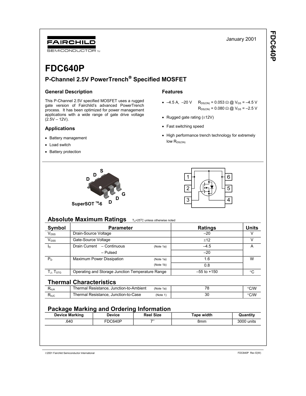
Page 1 Text Content
FD 640P
January 2001
FDC640P P-Channel 2.5V Power Trench Specified MOSFET General Description Features This P-Channel 2.5V specified MOSFET uses a rugged
• –4.5 A, –20 V RDS(ON) = 0.053 Ω @ VGS = –4.5 V
gate version of Fairchild’s advanced Power Trench
RDS(ON) = 0.080 Ω @ VGS = –2.5 V
process. It has been optimized for power management applications with a wide range of gate drive voltage
• Rugged gate rating (±12V)
• Fast switching speed
Applications
• High performance trench technology for extremely
• Battery management
low RDS(ON)
• Load switch • Battery protection
Super SOT -6TM
Absolute Maximum Ratings TA=25o C unless otherwise noted Symbol Parameter Ratings Units VDSS Drain-Source Voltage –20 VGSS Gate-Source Voltage ±12 ID Drain Current – Continuous (Note 1a) –4.5
– Pulsed –20
Maximum Power Dissipation (Note 1a) 1.6 WPD
(Note 1b) 0.8
TJ, TSTG Operating and Storage Junction Temperature Range –55 to +150 °C
Thermal Characteristics
RθJA Thermal Resistance, Junction-to-Ambient (Note 1a) °C/W RθJC Thermal Resistance, Junction-to-Case (Note 1) °C/W
Package Marking and Ordering Information Device Marking Device Reel Size Tape width Quantity .640 FDC640P 7’’ 8mm 3000 units
2001 Fairchild Semiconductor International FDC640P Rev E(W)
Page Summary Contents For Fairchild FDC640P User Guide
Manual Details
| Brand | Fairchild |
|---|---|
| Pages | 5 |
| File Size | 78.23 KB |
| Published | July 22, 2026 |
Enter the captcha to get the download link:

Frequently Asked Questions
What is the maximum continuous drain current (ID)?
The maximum continuous drain current rating is -4.5 A.
Under what temperatures can this component operate?
The operating junction temperature range is from -55 to +150 °C.
How resistant is the MOSFET to thermal stress?
Its thermal resistance, junction-to-ambient (θJA), is 78 °C/W when mounted on a specified pad on an FR-4 board.
What electrical applications is this component optimized for?
It is optimized for power management applications such as high-performance trench technology, battery management, load switch, and battery protection.