Fairchild FCP13N60N FCPF13N60NT User's Manual
Summary
Discover this high-performance N-Channel SuperMOS MOSFET, engineered for demanding power conversion applications requiring efficiency and durability. Featuring ultra-low gate charge and superior switching performance up to 600V/13A, it is ideal for AC-DC SMPS, PFC circuits, server networking, and industrial power supplies. This technical document provides comprehensive specifications, including electrical ratings, thermal characteristics, and detailed operating parameters, allowing engineers to reliably integrate this robust component into next-generation power management systems.
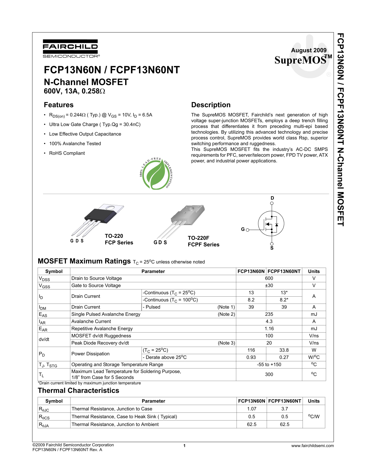
Page 1 Text Content
FC P13N 60N / FC PF13N 60N T N -C hannel M SFET
August 2009
Supre MOSTM
FCP13N60N / FCPF13N60NT N-Channel MOSFET 600V, 13A, 0.258Ω Features Description RDS(on) = 0.244Ω ( Typ.) @ VGS = 10V, ID = 6.5A The Supre MOS MOSFET, Fairchild’s next generation of high
voltage super-junction MOSFETs, employs a deep trench filling
Ultra Low Gate Charge ( Typ.Qg = 30.4n C)
process that differentiates it from preceding multi-epi based technologies. By utilizing this advanced technology and precise
Low Effective Output Capacitance
process control, Supre MOS provides world class Rsp, superior 100% Avalanche Tested switching performance and ruggedness. This Supre MOS MOSFET fits the industry’s AC-DC SMPS
Ro HS Compliant
requirements for PFC, server/telecom power, FPD TV power, ATX power, and industrial power applications.
TO-220
TO-220F
FCP Series G D S S D
FCPF Series G
MOSFET Maximum Ratings TC = 25o C unless otherwise noted Symbol Parameter FCP13N60N FCPF13N60NT Units VDSS Drain to Source Voltage
VGSS Gate to Source Voltage ±30
-Continuous (TC = 25o C) 13*
ID Drain Current
-Continuous (TC = 100o C) 8.2 8.2*
IDM Drain Current - Pulsed (Note 1) 39 39 A EAS Single Pulsed Avalanche Energy (Note 2) m J IAR Avalanche Current 4.3 EAR Repetitive Avalanche Energy 1.16 m J MOSFET dv/dt Ruggedness V/ns
dv/dt
Peak Diode Recovery dv/dt (Note 3) V/ns
(TC = 25o C) 33.8
PD Power Dissipation
- Derate above 25o C 0.93 0.27 W/o C
TJ, TSTG Operating and Storage Temperature Range -55 to +150 Maximum Lead Temperature for Soldering Purpose, o C
1/8” from Case for 5 Seconds
*Drain current limited by maximum junction temperature
Thermal Characteristics Symbol Parameter FCP13N60N FCPF13N60NT Units
RθJC Thermal Resistance, Junction to Case 1.07 3.7
o C/WRθCS
Thermal Resistance, Case to Heak Sink ( Typical) 0.5 0.5 RθJA Thermal Resistance, Junction to Ambient 62.5 62.5
©2009 Fairchild Semiconductor Corporation www.fairchildsemi.com1 FCP13N60N / FCPF13N60NT Rev. A
Page Summary Contents For Fairchild FCP13N60N FCPF13N60NT User's Manual
Manual Details
| Brand | Fairchild |
|---|---|
| Pages | 10 |
| File Size | 898.68 KB |
| Published | July 16, 2026 |
Enter the captcha to get the download link:

Frequently Asked Questions
What is the typical drain-to-source on resistance for this MOSFET?
The static drain-to-source on resistance ($R_{DS(on)}$) is typically 0.244Ω when measured at $V = 10V$ and $I = 6.5A$.
What power applications are suitable for this SupreMOS MOSFET?
The device is RoHS compliant and suitable for PFC, server/telecom power, FPD TV power, ATX power, and industrial power applications.
How should I adjust calculations if operating above 25°C?
Power Dissipation ($P_D$) must be derated when the operating temperature exceeds 25°C. The datasheet provides a derating factor for this calculation.