# A B C D E F G H I J K L M N O P Q R S T U V W X Y Z

Fairchild AN4107 User's Guide

Summary

Essential technical documentation for implementing high-efficiency power factor correction (PFC) using the FAN7527 active control controller within boost converter designs. This manual thoroughly explains the PFC mechanism, detailing how a sophisticated internal multiplier forces the input current to perfectly track sinusoidal AC line voltage. It provides engineers with comprehensive insights into the chip's operation, including detailed block diagrams and critical over-voltage protection modes (Soft OVP, Dynamic/Static OVP). Ideal for power electronics designers building systems that require superior power quality and compliance with modern electrical standards.
📄 Preview PAGE OF 14

Page 1 Text Content

www.fairchildsemi.com

Application Note AN4107 Design of Power Factor Correction Using FAN7527

1. Introduction power factor is obtained.

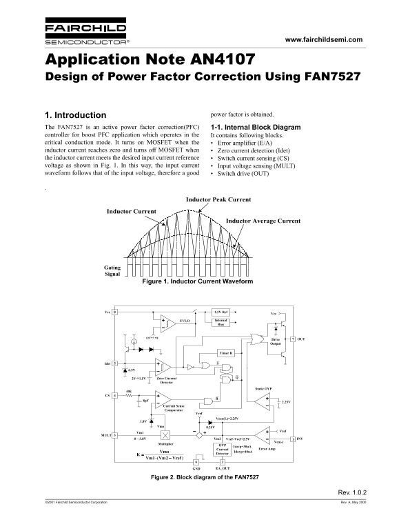
The FAN7527 is an active power factor correction(PFC) 1-1. Internal Block Diagram controller for boost PFC application which operates in the It contains following blocks. critical conduction mode. It turns on MOSFET when the Error amplifier (E/A) inductor current reaches zero and turns off MOSFET when Zero current detection (Idet) the inductor current meets the desired input current reference Switch current sensing (CS) voltage as shown in Fig. 1. In this way, the input current Input voltage sensing (MULT) waveform follows that of the input voltage, therefore a good Switch drive (OUT)

Inductor Peak Current

Inductor Current

Inductor Average Current

Gating Signal

Figure 1. Inductor Current Waveform

8Vcc 2.5V Ref

UVLO Internal Bias

12V 9V OUTDrive

Output

Timer R

2V 1.5V Zero Current Detector

Static OVP

Current Sense Comparator

Veao(L)=2.25V

Vmo 0.25V

Vm1 +−

0 ~ 3.8V Vm2 Vref~Vref+2.5V INV1

Vea(-)

Multiplier OVP

Isovp=30u A

Current Error Amp

Vmo K Idovp=40u A

Detector

−⋅ Vref2Vm1Vm

GND EA_OUT

Figure 2. Block diagram of the FAN7527

Rev. 1.0.2

©2001 Fairchild Semiconductor Corporation Rev. A, May 2000

Page Summary Contents For Fairchild AN4107 User's Guide

Page 1 www.fairchildsemi.com Application Note AN4107 Design of Power Factor Correction Using FAN7527 1. Introduction power factor is obtained. The FAN7527 is an active power factor correction(PFC) 1-1. Inter...
Page 2 AN4107 APPLICATION NOTE 2. Device Block Description OVP is added. The FAN7527 monitors the current flowing into the EA_OUT pin. If the monitored current reaches about 2-1. Error Amplifier and Over Vol...
Page 3 APPLICATION NOTE AN4107 Current Sense Comparator Vref OVP Veao(L)=2.25V Vmo 0.25V Vm1 Vref 0 ~ 3.8V Vm2 Vref~Vref+2.5V INV1 Vea(-) Multiplier Isovp=30u A Current Error Amp Vmo K Idovp=40u A Detector −...
Page 4 AN4107 APPLICATION NOTE 2-4. Zero Current Detector provided. The zero current detector input is protected internally by two clamps. The upper 6.5V clamp prevents FAN7527 operates as a critical conduct...
Page 5 APPLICATION NOTE AN4107 2) Auxiliary winding design IL t( 2Iin ωt( )sin peak( peak( toff ------------------------------------------------------- (2)= The auxiliary winding voltage is lowest at the hig...
Page 6 AN4107 APPLICATION NOTE ai Ai PFC Ci AV a V Circuit Input Filter Figure 8. Input voltage and current displacement due to input filter capacitance 4) Output capacitor design IO The output capacitor is ...
Page 7 APPLICATION NOTE AN4107 Diode average current can be calculated by (21). The total diode loss can be calculated by (22) and then a diode can be Rin2 VPIN3 Vin ---------------------------⋅= selected co...
Page 8 AN4107 APPLICATION NOTE capacitor value is 0.56u F. And the maximum input 4-6. Zero current detection resistor design capacitance is restricted by IDF. The calculated value is The calculate value is 4...
Page 9 APPLICATION NOTE AN4107 Table 1: 100W demo board part list Part# Value Note Part# Value Note Fuse Capacitor F1 250V/3A C1 47n F 275Vac Varistor C2 150n F 275Vac NTC C5 0.47n F 630V RT1 10D-9 C6 47n F ...
Page 10 AN4107 APPLICATION NOTE Table 2: 150W demo board part list Part# Value Note Part# Value Note Fuse Capacitor F1 250V/3A C1 330n F 275Vac Varistor C2 330n F 275Vac NTC C5 0.68n F 630V RT1 10D-9 C6 47n F...
Page 11 APPLICATION NOTE AN4107 Table 3: 200W demo board part list Part# Value Note Part# Value Note Fuse Capacitor F1 250V/3A C1 330n F 275Vac Varistor C2 330n F 275Vac NTC C5 0.68n F 630V RT1 10D-9 C6 47n F...
Page 12 AN4107 APPLICATION NOTE Nomenclature IL(peak) (t) : inductor current peak value during one switching f SW : switching frequency cycle f SW(max) : maximum switching frequency IL(peak) : inductor curren...
Page 13 APPLICATION NOTE AN4107 ©2001 Fairchild Semiconductor Corporation
Page 14 AN4107 APPLICATION NOTE DISCLAIMER FAIRCHILD SEMICONDUCTOR RESERVES THE RIGHT TO MAKE CHANGES WITHOUT FURTHER NOTICE TO ANY PRODUCTS HEREIN TO IMPROVE RELIABILITY, FUNCTION OR DESIGN. FAIRCHILD DOES N...

Manual Details

Brand Fairchild
Pages 14
File Size 486.37 KB
Published June 05, 2026
39 views

Enter the captcha to get the download link:

captcha

Frequently Asked Questions

What is the primary purpose of the FAN7527 controller?

It is an active power factor correction (PFC) controller designed for boost PFC applications.

How does the device protect against over voltage conditions?

If the monitored current exceeds 40uA, the OVP protection triggers and switches off the transistor until the current drops below approximately 10uA.

What mechanism forces the input current to be sinusoidal?

The multiplier output controls the comparator threshold voltage, allowing the peak inductor current to follow the AC line and forcing the average input current to be sinusoidal.