ESTES 2029 Converter User's Manual
Summary
Build your ultimate multi-stage model rocket with this comprehensive kit and instructional manual. This guide walks hobbyists through assembling various configurations, including attaching fin units, securing nose cones, mounting recovery parachutes/shroud lines, and preparing engines. The manual details step-by-step assembly, essential pre-launch checks, and adherence to NAR safety protocols, making it the perfect resource for rocketry enthusiasts of all skill levels.
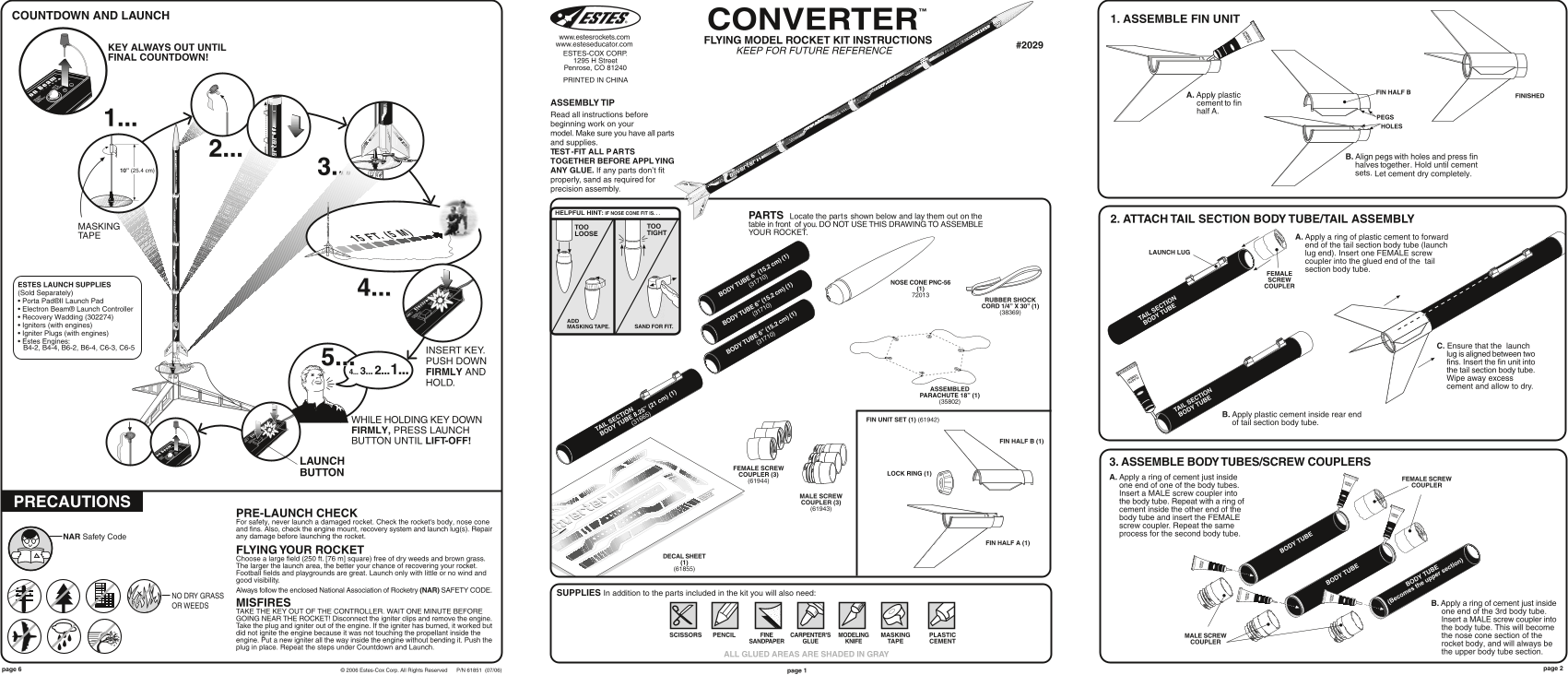
Page 1 Text Content
COUNTDOWN AND LAUNCH
1. ASSEMBLE FIN UNIT
CONVERTER™ FLYING MODEL ROCKET KIT INSTRUCTIONSwww.estesrockets.com
www.esteseducator.com #2029
KEY ALWAYS OUT UNTIL
KEEP FOR FUTURE REFERENCE
ESTES-COX CORP.
FINAL COUNTDOWN!
1295 H Street Penrose, CO 81240 PRINTED IN CHINA
FIN HALF B
A. Apply plastic FINISHED ASSEMBLY TIP cement to fin half A.
Read all instructions before
1... beginning work on your
HOLES
model. Make sure you have all parts and supplies. 2... TEST -FIT ALL PARTS
CEMENT MODEL B. Align pegs with holes and press fin
TOGETHER BEFORE APPLYING
halves together. Hold until cement
10” (25.4 cm) 3... ANY GLUE. If any parts don’t fit
sets. Let cement dry completely.
properly, sand as required for
CEMENT MODEL precision assembly.
HELPFUL HINT: IF NOSE CONE FIT IS. . .
PARTS Locate the parts shown below and lay them out on the
2. ATTACH TAIL SECTION BODY TUBE/TAIL ASSEMBLY
TOO table in front of you. DO NOT USE THIS DRAWING TO ASSEMBLE
MASKING TOO
LOOSE TIGHT YOUR ROCKET.
TAPE A. Apply a ring of plastic cement to forward
15 FT. (5 M)
end of the tail section body tube (launch
LAUNCH LUG lug end). Insert one FEMALE screw
coupler into the glued end of the tail section body tube.
FEMALE SCREW
NOSE CONE PNC-56
ESTES LAUNCH SUPPLIES (31710) COUPLER
(Sold Separately) 4... BODY TUBE 6” (15.2 cm) (1
PLASTIC CEMENT RUBBER SHOCK
• Porta Pad®II Launch Pad
CORD 1/4” X 30” (1)
• Electron Beam® Launch Controller
• Recovery Wadding (302274) TAIL SECTION
BODY TUBE 6” (15.2 cm) (1 BODY TUBE
• Igniters (with engines) MASKING TAPE. SAND FOR FIT. • Igniter Plugs (with engines) • Estes Engines: (31710)
B4-2, B4-4, B6-2, B6-4, C6-3, C6-5 C. Ensure that the launch
INSERT KEY. BODY TUBE 6” (15.2 cm) (1
lug is aligned between two
PUSH DOWN fins. Insert the fin unit into
4... 3... 2... 1...5... FIRMLY AND the tail section body tube. Wipe away excess
HOLD.
cement and allow to dry.
ASSEMBLED PARACHUTE 18” (1) (35802)
TAIL SECTION
BODY TUBE B. Apply plastic cement inside rear end
WHILE HOLDING KEY DOWN FIN UNIT SET (1) (61942)
(31665) of tail section body tube.
FIRMLY, PRESS LAUNCH TAIL SECTION BODY TUBE 8.25” (21 cm) (1
BUTTON UNTIL LIFT-OFF! FIN HALF B (1)
LAUNCH 3. ASSEMBLE BODY TUBES/SCREW COUPLERS
FEMALE SCREW
BUTTON COUPLER (3) LOCK RING (1)
A. Apply a ring of cement just inside FEMALE SCREW
one end of one of the body tubes. COUPLER
Insert a MALE screw coupler into
MALE SCREW
PRECAUTIONS COUPLER (3) the body tube. Repeat with a ring of
(61943) cement inside the other end of the
PRE-LAUNCH CHECK
body tube and insert the FEMALE
For safety, never launch a damaged rocket. Check the rocket's body, nose cone
screw coupler. Repeat the same
and fins. Also, check the engine mount, recovery system and launch lug(s). Repair
process for the second body tube.
NAR Safety Code any damage before launching the rocket.
FIN HALF A (1)
FLYING YOUR ROCKET BODY TUBE
DECAL SHEET
Choose a large field (250 ft. [76 m] square) free of dry weeds and brown grass.
The larger the launch area, the better your chance of recovering your rocket.
(61855) ectio
Football fields and playgrounds are great. Launch only with little or no wind and good visibility.
BODY TUBE BODY TUBE e upper s
Always follow the enclosed National Association of Rocketry (NAR) SAFETY CODE.
SUPPLIES In addition to the parts included in the kit you will also need:
NO DRY GRASS
MISFIRES (Becomes th B. Apply a ring of cement just inside
OR WEEDS
TAKE THE KEY OUT OF THE CONTROLLER. WAIT ONE MINUTE BEFORE one end of the 3rd body tube. GOING NEAR THE ROCKET! Disconnect the igniter clips and remove the engine. Insert a MALE screw coupler into Take the plug and igniter out of the engine. If the igniter has burned, it worked but the body tube. This will become did not ignite the engine because it was not touching the propellant inside the
SCISSORS PENCIL FINE CARPENTER'S MODELING MASKING PLASTIC MALE SCREW the nose cone section of the
engine. Put a new igniter all the way inside the engine without bending it. Push the SANDPAPER GLUE KNIFE TAPE CEMENT COUPLER
rocket body, and will always be
plug in place. Repeat the steps under Countdown and Launch.
the upper body tube section.
ALL GLUED AREAS ARE SHADED IN GRAY
© 2006 Estes-Cox Corp. All Rights Reserved P/N 61851 (07/06) page 1page 6
ST IC PL EN EM
Page Summary Contents For ESTES 2029 Converter User's Manual
Manual Details
| Brand | Estes |
|---|---|
| Pages | 2 |
| File Size | 712.53 KB |
| Published | June 03, 2026 |
Enter the captcha to get the download link:

Frequently Asked Questions
What is required for safe launch preparation?
Always follow the enclosed National Association of Rocketry (NAR) SAFETY CODE and pre-launch safety checks on all rocket components.
How do I assemble a multi-section rocket body?
You can easily change length by screwing different body tube sections together to create 2, 3, or 4-piece rockets.
Where should decals be applied?
Apply decals only when you are outside at the launch site, preparing to launch, and when assembling as a 4-piece rocket.
What steps must I take if an igniter has burned out but didn't ignite the engine?
Take the plug and igniter out; put a new igniter all the way inside without bending it, and repeat the countdown and launch procedures.