EMERSON Instruction Sheet GA-5058, EXPC100-LLT Power Connection Kit
Summary
The EXPC100-LLT Power Connection Kit provides a robust transition point for connecting self-regulating heater cable (LLT/UT-2) to customer power wiring in industrial applications. This kit is rated IP66/NEMA 4X, ensuring reliable performance even in harsh environments. The included manual serves as a comprehensive guide for professionals, detailing every step from preparing the heater cable core and bus wires, to installing both end terminations and robust power terminals using durable silicone adhesive. It guarantees proper installation of complex heat tracing systems according to industrial standards.
Page 1 Text Content
NELSON
INSTALLATION
EXPC100-LLT POWER CONNECTION KIT INSTRUCTIONS
DESCRIPTION The EXPC100-LLT Power Connection Kit is designed for terminating one heater cable to customer supplied power wiring. This kit is designed for use with all wattages of LLT and UT-2 heater cables. The EXPC100-LLT is rated IP66/NEMA 4X and provides threaded entries compatible with M25 ISO thread standards. Standard terminal blocks are sized for maximum 10mm ( 6 AWG ) power wires.
These instructions are to be used together with the installation and maintenance instructions for self-regulating heater cable (GA-1765).
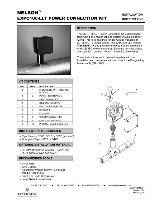
KIT CONTENTS QTY ITEM DESCRIPTION 1 1 ENCLOSURE WITH TERMINAL
BLOCKS
1 2 POWER TERMINATION 1 3 END TERMINATION 1 4 SILICONE ADHESIVE 1 5 ENCLOSURE ADAPTER 1 6 STANDOFF 1 7 LOCKNUT 1 8 GREEN/YELLOW TUBE 1 9 CABLE TIE (not shown) 1 10 PRODUCT LABEL (not shown)
INSTALLATION ACCESSORIES Pipe Clamp – PC03, PC12 or PC20 (included) Fiberglass Tape – GT6 or GT60
OPTIONAL INSTALLATION MATERIAL HC-SPA Small Pipe Adapter – For 25 mm (1.0”) diameter pipe and below.
RECOMMENDED TOOLS Utility Knife Wire Cutters Adjustable Wrench (52mm [2.1”] size) Needle Nose Pliers Small Flat Blade Screwdriver Large Slotted Screwdriver
TULSA, OK 74101 TEL 918-627-5530 FAX 918-641-7336 www.nelsonheaters.com
GA-5058 Rev. 1 Sheet 1 of 8 March 2016
Page Summary Contents For EMERSON Instruction Sheet GA-5058, EXPC100-LLT Power Connection Kit
Manual Details
| Brand | Emerson |
|---|---|
| Pages | 8 |
| File Size | 637.13 KB |
| Published | June 06, 2026 |
Enter the captcha to get the download link:

Frequently Asked Questions
How long must I wait before testing the circuit after installation?
Do not megger or hipot until the silicone adhesive has completely cured, which takes approximately 24 hours.
What is the required maximum size for power wires used in this kit?
The standard terminal blocks are sized to accommodate a maximum of 10mm (6 AWG) power wires.
What must I be careful about during heater cable preparation?
Do not cut, nick, or damage the bus wires, and avoid cutting the braid while prepping the overall cable.
What safety measure is necessary to prevent heat problems in operation?
You must take measures to avoid dust accumulation inside the standoff, as this could violate temperature certification.