Delta Industrial Automation Inverter BUE Series Brake Module Optional Accessory
Summary
This comprehensive manual provides technical documentation for DELTA's Brake Units (BUE) and associated brake resistors designed for VFD-E/VFD-EL AC motor drives. It explains how the BUE system efficiently absorbs regenerative energy, ensuring safe and reliable deceleration when controlling three-phase induction motors. The guide is essential reading for electrical technicians and industrial automation engineers, covering detailed wiring requirements, component compatibility matrices, safety warnings, and proper installation procedures to guarantee optimal motor control performance in critical applications.
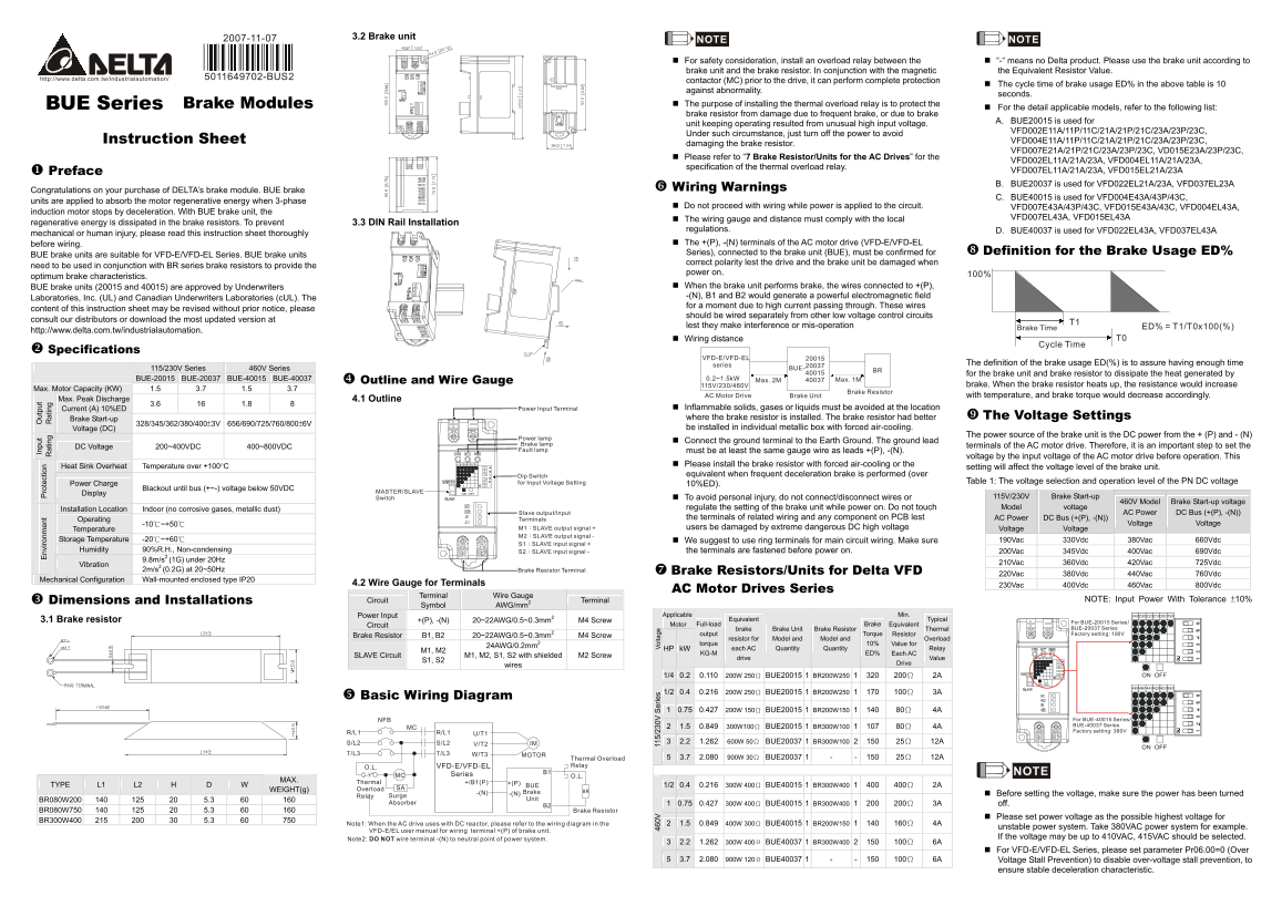
Page 1 Text Content
2007-11-07 3.2 Brake unit
In pu ut pu NOTE NOTE
nv iro nm en ro te ct io
at in at in
For safety consideration, install an overload relay between the “-“ means no Delta product. Please use the brake unit according to brake unit and the brake resistor. In conjunction with the magnetic the Equivalent Resistor Value.
5011649702-BUS2
contactor (MC) prior to the drive, it can perform complete protection
The cycle time of brake usage ED% in the above table is 10
against abnormality.
seconds.
BUE Series Brake Modules The purpose of installing the thermal overload relay is to protect the
For the detail applicable models, refer to the following list:
brake resistor from damage due to frequent brake, or due to brake
A. BUE20015 is used for
unit keeping operating resulted from unusual high input voltage.
VFD002E11A/11P/11C/21A/21P/21C/23A/23P/23C,
Under such circumstance, just turn off the power to avoid
Instruction Sheet VFD004E11A/11P/11C/21A/21P/21C/23A/23P/23C,
damaging the brake resistor.
VFD007E21A/21P/21C/23A/23P/23C, VD015E23A/23P/23C,
Please refer to “7 Brake Resistor/Units for the AC Drives” for the
VFD002EL11A/21A/23A, VFD004EL11A/21A/23A,
specification of the thermal overload relay.
Preface VFD007EL11A/21A/23A, VFD015EL21A/23A B. BUE20037 is used for VFD022EL21A/23A, VFD037EL23A
Congratulations on your purchase of DELTA’s brake module. BUE brake Wiring Warnings
C. BUE40015 is used for VFD004E43A/43P/43C,
units are applied to absorb the motor regenerative energy when 3-phase
Do not proceed with wiring while power is applied to the circuit. VFD007E43A/43P/43C, VFD015E43A/43C, VFD004EL43A,
induction motor stops by deceleration. With BUE brake unit, the
The wiring gauge and distance must comply with the local VFD007EL43A, VFD015EL43A
regenerative energy is dissipated in the brake resistors. To prevent 3.3 DIN Rail Installation
regulations. D. BUE40037 is used for VFD022EL43A, VFD037EL43A
mechanical or human injury, please read this instruction sheet thoroughly
before wiring. The +(P), -(N) terminals of the AC motor drive (VFD-E/VFD-EL
Series), connected to the brake unit (BUE), must be confirmed for Definition for the Brake Usage ED%
BUE brake units are suitable for VFD-E/VFD-EL Series. BUE brake units
correct polarity lest the drive and the brake unit be damaged when
need to be used in conjunction with BR series brake resistors to provide the
power on. 100%
optimum brake characteristics.
BUE brake units (20015 and 40015) are approved by Underwriters When the brake unit performs brake, the wires connected to +(P), -(N), B1 and B2 would generate a powerful electromagnetic field
Laboratories, Inc. (UL) and Canadian Underwriters Laboratories (c UL). The
for a moment due to high current passing through. These wires
content of this instruction sheet may be revised without prior notice, please
should be wired separately from other low voltage control circuits
consult our distributors or download the most updated version at
lest they make interference or mis-operation ED% = T1/T0x100(%)
Brake Time
http://www.delta.com.tw/industrialautomation.
Wiring distance T0
Cycle Time
Specifications
VFD-E/VFD-EL
series The definition of the brake usage ED(%) is to assure having enough time
115/230V Series 460V Series BRBUE-
for the brake unit and brake resistor to dissipate the heat generated by
BUE-20015 BUE-20037 BUE-40015 BUE-40037 Outline and Wire Gauge 0.2~1.5k W Max. 2M Max. 1M
115V/230/460V brake. When the brake resistor heats up, the resistance would increase
Max. Motor Capacity (KW) 1.5 3.7 1.5 3.7
Brake Resistor
AC Motor Drive Brake Unit with temperature, and brake torque would decrease accordingly.
Max. Peak Discharge 4.1 Outline
Current (A) 10%ED 3.6 16 1.8 8 Power Input Terminal Inflammable solids, gases or liquids must be avoided at the location
Brake Start-up where the brake resistor is installed. The brake resistor had better The Voltage Settings
Voltage (DC) 328/345/362/380/400±3V 656/690/725/760/800±6V be installed in individual metallic box with forced air-cooling.
The power source of the brake unit is the DC power from the + (P) and - (N)
Power lamp
Connect the ground terminal to the Earth Ground. The ground lead
Brake lamp terminals of the AC motor drive. Therefore, it is an important step to set the
DC Voltage 200~400VDC 400~800VDC
Fault lamp must be at least the same gauge wire as leads +(P), -(N).
voltage by the input voltage of the AC motor drive before operation. This
Heat Sink Overheat Temperature over +100°C Please install the brake resistor with forced air-cooling or the
setting will affect the voltage level of the brake unit.
Dip Switch equivalent when frequent deceleration brake is performed (over
for Input Voltage Setting Table 1: The voltage selection and operation level of the PN DC voltage
Power Charge 10%ED).
Display Blackout until bus (+~-) voltage below 50VDC MASTER/SLAVE OFFON
Switch To avoid personal injury, do not connect/disconnect wires or 115V/230V Brake Start-up
460V Model Brake Start-up voltage
Installation Location Indoor (no corrosive gases, metallic dust) regulate the setting of the brake unit while power on. Do not touch Model voltage
Slave output/input AC Power DC Bus (+(P), -(N))
Operating Terminals the terminals of related wiring and any component on PCB lest AC Power DC Bus (+(P), -(N))
Voltage Voltage
Temperature -10℃~+50℃ M1 SLAVE output signal + users be damaged by extreme dangerous DC high voltage Voltage Voltage
M2 SLAVE output signal -
Storage Temperature -20℃~+60℃ We suggest to use ring terminals for main circuit wiring. Make sure 190Vac 330Vdc 380Vac 660Vdc
S1 SLAVE input signal +
Humidity 90%R.H., Non-condensing S2 SLAVE input signal - the terminals are fastened before power on. 200Vac 345Vdc 400Vac 690Vdc
Vibration 9.8m/s2 (1G) under 20Hz 210Vac 360Vdc 420Vac 725Vdc
2m/s2 (0.2G) at 20~50Hz Brake Resistor Terminal Brake Resistors/Units for Delta VFD
220Vac 380Vdc 440Vac 760Vdc
Mechanical Configuration Wall-mounted enclosed type IP20
4.2 Wire Gauge for Terminals 230Vac 400Vdc 460Vac 800Vdc
AC Motor Drives Series
Wire Gauge
Dimensions and Installations Circuit Terminal NOTE: Input Power With Tolerance ±10%
Symbol AWG/mm2 Terminal
Power Input Applicable Min.
3.1 Brake resistor Equivalent Typical
For BUE-20015 Series/
Circuit +(P), -(N) 20~22AWG/0.5~0.3mm2 M4 Screw Motor Full-load Brake Equivalent
brake Brake Unit Brake Resistor Thermal BUE-20037 Series output Torque Resistor Factory setting: 190V
Brake Resistor B1, B2 20~22AWG/0.5~0.3mm2 M4 Screw
resistor for Model and Model and Overload
torque 10% Value for
24AWG/0.2mm2
HP k W each AC Quantity Quantity Relay
KG-M ED% Each AC
SLAVE Circuit M1, M2 M1, M2, S1, S2 with shielded M2 Screw
0V 5/ 0V er ie Vo lta ge drive Value
Drive
wires
1/4 0.2 0.110 200W 250Ω BUE20015 BR200W250 200Ω 2A OFFON
OFFON
1/2 0.4 0.216 200W 250Ω BUE20015 BR200W250 100Ω 3A
Basic Wiring Diagram
0.75 0.427 200W 150Ω BUE20015 BR200W150 80Ω 4A
NFB For BUE-40015 Series/ 1.5 0.849 300W100Ω BUE20015 BR300W100 80Ω 4A BUE-40037 Series
R/L1 R/L1 Factory setting: 380V
S/L2 S/L2 IM 2.2 1.262 600W 50Ω BUE20037 BR300W100 25Ω 12A 11
OFFON
T/L3 T/L3 W/T3 MOTOR
Thermal Overload 3.7 2.080 900W 30Ω BUE20037 - - 25Ω 12A
O.L. VFD-E/VFD-EL Relay
Series B1 NOTE
MC O.L.
Thermal +/B1
TYPE L1 L2 H D W MAX. BUE 1/2 0.4 0.216 300W 400Ω BUE40015 BR300W400 400Ω 2A
WEIGHT(g) Overload SA
Brake BR
Relay Surge Before setting the voltage, make sure the power has been turned
BR080W200 140 125 20 5.3 60 160 Unit
Absorber 0.75 0.427 300W 400Ω BUE40015 BR300W400 200Ω 3A off.
BR080W750 140 125 20 5.3 60 160 Brake Resistor
Please set power voltage as the possible highest voltage for
BR300W400 215 200 30 5.3 60 750
Note1: When the AC drive uses with DC reactor, please refer to the wiring diagram in the 1.5 0.849 400W 300Ω BUE40015 BR200W150 160Ω 4A
unstable power system. Take 380VAC power system for example.
VFD-E/EL user manual for wiring terminal +(P) of brake unit.
Note2: wire terminal -(N) to neutral point of power system.DO NOT If the voltage may be up to 410VAC, 415VAC should be selected.
2.2 1.262 300W 400Ω BUE40037 BR300W400 100Ω 6A
For VFD-E/VFD-EL Series, please set parameter Pr06.00=0 (Over
3.7 2.080 900W 120Ω BUE40037 - - 100Ω 6A Voltage Stall Prevention) to disable over-voltage stall prevention, to
ensure stable deceleration characteristic.
Page Summary Contents For Delta Industrial Automation Inverter BUE Series Brake Module Optional Accessory
Manual Details
| Brand | Delta |
|---|---|
| Pages | 2 |
| File Size | 881.64 KB |
| Published | June 06, 2026 |
Enter the captcha to get the download link:

Frequently Asked Questions
What components are needed for safe brake unit installation?
You must install an overload relay (e.g., MC) and use the corresponding brake resistor with the brake unit.
How is the brake usage cycle time calculated?
ED% = T1/T0 x 100(%), where ED% is the duty cycle, and T1 and T0 are the respective times in seconds.
What precautions must be taken during wiring?
Do not proceed with wiring while power is applied to the circuit. The +(P) and -(N) terminals must maintain correct polarity.
Where should the brake unit be installed for optimal performance?
It must be mounted in an individual metallic box with forced air-cooling, away from inflammable solids or gases.
What should happen if frequent braking causes issues?
Frequent deceleration can damage the brake resistor and decrease brake torque. Use the correct model listed for your VFD series.