Delta Industrial Automation Inverter EME-PG01 PG Speed Feedback Card (For E Series) Optional Accessory
Summary
This specialized pulse generator card is designed for industrial automation professionals integrating encoders and variable speed feedback into Delta VFD-E series Variable Frequency Drives. It ensures reliable signal transmission by supporting multiple encoder output types, including voltage, open collector, line driver, and complementary outputs. The associated manual provides detailed installation guides, comprehensive wiring diagrams, terminal specifications, and critical operational safety warnings (e.g., proper shielding cable use and power requirements) to ensure accurate setup and maximum system lifespan for control integrators and maintenance technicians.
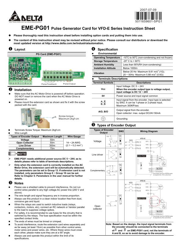
Page 1 Text Content
5011659601-SPG1
EME-PG01 Pulse Generator Card for VFD-E Series Instruction Sheet Please thoroughly read this instruction sheet before installing option cards and putting them into use. The content of this instruction sheet may be revised without prior notice. Please consult our distributors or download the most updated version at http://www.delta.com.tw/industrialautomation. Layout Specification
Environmental
PG Card (EME-PG01)
Operating Temperature -10o C to 50o C (non-condensing and not frozen) Storage Temperature -20o C to + 60o C Ambient Humidity Less than 90%RH (non-condensing) Installation Altitude Below 1000m
Vibration Below 20 Hz: Maximum 9.81 m/s2 (1G);
20 ~ 50Hz: Maximum 5.88 m/s2 (0.6G)
Terminals Descriptions Terminal Symbols Descriptions
Pulse Feedback Pulse Output
Input Voltage: DC 5 ~ 24V
Vcc When the encoder output type is voltage output,
Installation
input voltage is DC 12 ~ 24V
Make sure that the AC Motor Drive is powered off before operation.
DO NOT insert or remove the card when the AC Motor Drive is 0V Power source and input signal common
powered on.
Input signal from the encoder. Input type is selected
Please mount the extension card as shown and fix it with the screw by SW2. It can be 1-phase or 2-phase input. packed with the card.
Maximum 300KP/sec
A/O, B/O Output signal from the encoder.
Open collector: max. output DC24V 50m A
Screw torque: Maximum 2kgf-cm Grounding
Types of Encoder Output
Terminals Screw Torque: Maximum 2kgf-cm Types of Encoder
SW2 Wiring Diagram
Wire Length Output
VCC OC
Types of Encoder Output Maximum Length Wire Gauge
VFD-E
Voltage 50m NFB
Voltage O/P U(T1)
Open Collector 50m 14 ~ 24 AWG
TP Motor
Line Driver 300m (2.1 ~ 0.2 mm2 ) 0V S(L2) 3~
Complementary 70m T(L3)
Line driver
EME-PG01 Vin
EME-PG01 needs additional power source DC 5 ~ 24V, as to PG GND
details please refer to table of terminals descriptions.
OC Vcc DC
OC 5~24V
Only when the extension card is correctly installed on the AC 0V
Motor Drive, the extension card will be automatically detected. A/O
The parameters can be set in Group 13. If extension card is not Complementary O/P RPM Meter
0V installed, only parameters Group 0 ~ Group 10 can be set. *The power source of RPM meter
0V TP
is supplied by the customers.
Refer to Chapter 5: Parameters in the user manual for further details.
VFD-E
Notes U(T1)
V(T2) Motor
Please use a shielded cable to prevent interference. Do not run S(L2)
control wires parallel to any high voltage AC power line (200 V and W(T3)
above).
The wire length and signal frequency are in inverse proportion. OC
Always use this product in a clean indoor location free from dust, EME-PG01 Vin
O/P PG
corrosive gas and liquid.
When the relays are used to switch inductive loads (relays, 0V
OC Vcc DC
Open 5~24V
contactors, motors, etc), connect an RC network or Varistor parallel 0V
collector
to the load to suppress voltage spikes.
TP A/O For safety, it is recommended to use fuses for the circuitry that is B/O
0V RPM Meter
switched by the relays. The fuse specification must be within the *The power source of RPM meter
is supplied by the customers.
specified contact limits. The ends of wires must be tinned or crimped.
To avoid interference, route the extension card wires separately and Note: Based on the design, the input signal terminals from as far away (at least 15cm) as possible from other control wires, the encoder should be connected to the terminals
motor wires and power wires, etc. Where these wires must cross of A and B on EME-PG01 card, not the terminals of each other, please make sure they are at a 90o angle.
A and B, so as to avoid damage to the encoder.
Always use and operate this product within the limit of its specifications.
Page Summary Contents For Delta Industrial Automation Inverter EME-PG01 PG Speed Feedback Card (For E Series) Optional Accessory
Manual Details
| Brand | Delta |
|---|---|
| Pages | 2 |
| File Size | 452.79 KB |
| Published | June 06, 2026 |
Enter the captcha to get the download link:

Frequently Asked Questions
如何確定是否安裝了擴展卡?
只有當擴展卡正確安裝到變頻器上時,變頻器才會自動偵測到它。
使用這款產品所需的附件和電氣保護措施是什麼?
用於開關感性負載(如繼電器、接觸器)時,需連接RC網路或Varistor;建議為RPM計數器的電路設置保險絲。
在佈線方面應注意哪些重要的抗干擾和安全注意事項?
使用屏蔽電纜以防止干擾;切勿讓控制線與高壓AC電源線並排,且必須保持獨立距離。