Dell Direct from Development – PowerEdge MX7000 LED Device Status Manual User Guide
Summary
Dell EMC PowerEdge MX7000 LED Device Status technical white paper. Comprehensive reference for all LED behaviors on MX7000 chassis and modular components including Management Module (power LED green, status LED blue/amber for health and identify functions), compute sleds, storage sleds, I/O modules, fans, and power supplies. Covers the Identify function activatable from front panel or remotely via OpenManage Enterprise Modular GUI, and device-specific LED features like MX5016s mapping state indication. Authored by Kristopher Gilly and Shashwat Jnawali.
Page 1 Text Content
Direct from Power Edge Product Group Development
Power Edge MX7000 LED Device Status
Users want to be able to look at the chassis and deduce its current health state when physically in front of the chassis. Most of the components that are present in the MX7000 chassis are able to display their current health
Tech Note by:
state via LEDs.
Kristopher Gilly
Users also want to be able to accurately identify components in a chassis.
Shashwat Jnawali A useful feature to do this is the Identify function that can be activated
from the front panel, or remotely via the Open Manage Enterprise Modular GUI. This can be a very useful feature when you are managing a multi- chassis setup and want to remotely identify a particular device in the pool.
SUMMARY Some devices also implement their own specific LED behavior, for
example Power Edge MX5016s implement an LED feature that indicates
The MX7000 chassis and
mapping state. This document will cover these features.
modular devices in a MX7000 chassis are equipped with multi-
Management Module LED Behavior
purpose LEDs which can indicate the current health state
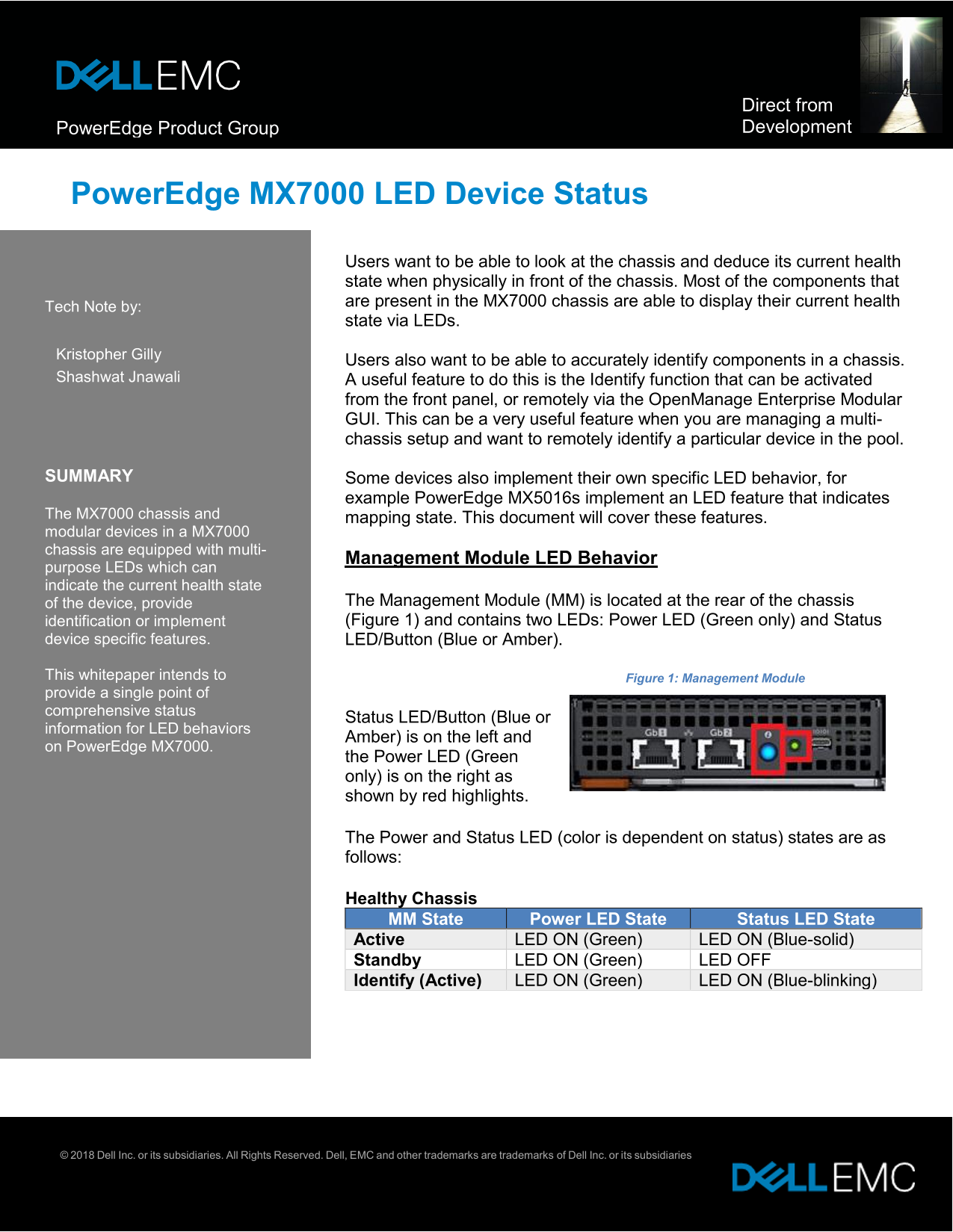
of the device, provide The Management Module (MM) is located at the rear of the chassis identification or implement (Figure 1) and contains two LEDs: Power LED (Green only) and Status
device specific features. LED/Button (Blue or Amber).
This whitepaper intends to Figure 1: Management Module provide a single point of comprehensive status
Status LED/Button (Blue or
information for LED behaviors
Amber) is on the left and
on Power Edge MX7000.
the Power LED (Green only) is on the right as shown by red highlights.
The Power and Status LED (color is dependent on status) states are as follows:
Healthy Chassis MM State Power LED State Status LED State Active LED ON (Green) LED ON (Blue-solid) Standby LED ON (Green) LED OFF Identify (Active) LED ON (Green) LED ON (Blue-blinking)
© 2018 Dell Inc. or its subsidiaries. All Rights Reserved. Dell, EMC and other trademarks are trademarks of Dell Inc. or its subsidiaries
Page Summary Contents For Dell Direct from Development – PowerEdge MX7000 LED Device Status Manual User Guide
Manual Details
| Brand | Dell |
|---|---|
| Pages | 4 |
| File Size | 319.38 KB |
| Published | July 03, 2026 |
Enter the captcha to get the download link:

Frequently Asked Questions
How can I identify components in the chassis remotely?
The Identify function can be activated from the front panel or remotely via the OpenManage Enterprise Modular GUI.
What does an Amber-blinking Status LED on the Management Module indicate?
An Amber-blinking status indicates a faulted chassis state.
How is a healthy Power Supply Unit (PSU) indicated using LEDs?
All four PSU LEDs (AC and DC Present, plus front/rear indicator LEDs) must be illuminated with green for a healthy status.
What does the Status LED do when an I/O Module has a fabric mismatch?
The green LED will blink for 2.5 seconds and then stay lit to indicate a fabric mismatch.