Dallas DS1045 4-Bit Dual Programmable Delay Line User's Manual & Specifications
Summary
Engineered for precision timing, this programmable silicon delay line offers a reliable alternative to traditional hybrid components. It accepts a single input signal and delivers two independently controllable outputs with selectable delays ranging from 9 ns up to 84 ns. This manual provides comprehensive technical specifications, including pin assignments for parallel programming (A0-A3/B0-B3), support for CMOS/TTL levels, and detailed timing diagrams. It is essential documentation for electronics designers and engineers needing highly accurate, repeatable signal delay in sensitive digital circuits.
Page 1 Text Content
查询DS1045供应商
DS1045
4-Bit Dual Programmable Delay Line
www.dalsemi.com
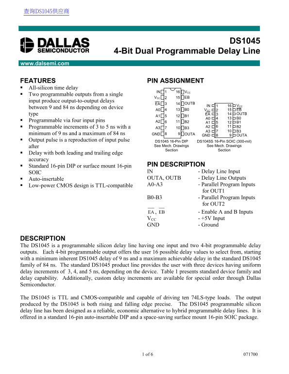
FEATURES PIN ASSIGNMENT All-silicon time delay
IN VCC
Two programmable outputs from a single
VCC EB
input produce output-to-output delays
EA OUTB
IN VCC161
between 9 and 84 ns depending on device
A0 B0 VCC EB
type EA OUTB
Programmable via four input pins A2
Programmable increments of 3 to 5 ns with a A2 B2
minimum of 9 ns and a maximum of 84 ns GND OUTA
GND OUTA
Output pulse is a reproduction of input pulse
DS1045 16-Pin DIP DS1045S 16-Pin SOIC (300-mil) after See Mech. Drawings See Mech. Drawings Section Section
Delay with both leading and trailing edge accuracy
Standard 16-pin DIP or surface mount 16-pin PIN DESCRIPTION SOIC IN - Delay Line Input Auto-insertable OUTA, OUTB - Delay Line Outputs Low-power CMOS design is TTL-compatible A0-A3 - Parallel Program Inputs
for OUT1
B0-B3 - Parallel Program Inputs
for OUT2
EA , EB - Enable A and B Inputs VCC - +5V Input GND - Ground
DESCRIPTION The DS1045 is a programmable silicon delay line having one input and two 4-bit programmable delay outputs. Each 4-bit programmable output offers the user 16 possible delay values to select from, starting with a minimum inherent DS1045 delay of 9 ns and a maximum achievable delay in the standard DS1045 family of 84 ns. The standard DS1045 product line provides the user with three devices having uniform delay increments of 3, 4, and 5 ns, depending on the device. Table 1 presents standard device family and delay capability. Additionally, custom delay increments are available for special order through Dallas Semiconductor.
The DS1045 is TTL and CMOS-compatible and capable of driving ten 74LS-type loads. The output produced by the DS1045 is both rising and falling edge precise. The DS1045 programmable silicon delay line has been designed as a reliable, economic alternative to hybrid programmable delay lines. It is offered in a standard 16-pin auto-insertable DIP and a space-saving surface mount 16-pin SOIC package.
1 of 6
Page Summary Contents For Dallas DS1045 4-Bit Dual Programmable Delay Line User's Manual & Specifications
Manual Details
| Brand | Dual |
|---|---|
| Pages | 6 |
| File Size | 93.49 KB |
| Published | June 05, 2026 |
Enter the captcha to get the download link:

Frequently Asked Questions
How is the maximum achievable delay determined?
The standard DS1045 family offers a maximum programmable delay of up to 84 ns.
What voltages are required to operate the device?
The DS1045 requires a +5V input (V) and uses TTL-compatible logic levels for programming inputs.
Is the output accurate for both rising and falling edges?
Yes, the delay is guaranteed to be accurate on both rising and falling edges within specified tolerances.
How can I program the custom delay values?
Delay values are set using four parallel input pins (A0-A3 or B0-B3) or latched via the enable inputs EA and EB.