ST M74HC4520 Dual 4-Bit Binary Counter Data Sheet
Summary
This high-speed M74HC4520 is a dual 4-bit binary counter built with robust CMOS technology. It provides reliable digital counting capabilities that can be easily cascaded in various circuits. The manual serves as a comprehensive guide for electronics engineers and designers, detailing full operating specifications, electrical characteristics, timing diagrams, and mechanical layouts. Whether you are integrating a simple counter or building complex sequential logic, this resource ensures optimal selection and implementation of the device.
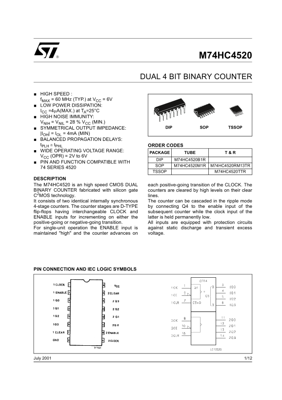
Page 1 Text Content
M74HC4520
DUAL 4 BIT BINARY COUNTER
HIGH SPEED : f MAX = 60 MHz (TYP.) at VCC = 6V LOW POWER DISSIPATION: ICC =4µA(MAX.) at TA=25°C HIGH NOISE IMMUNITY: VNIH = VNIL = 28 % VCC (MIN.)
SYMMETRICAL OUTPUT IMPEDANCE: SOP TSSOPDIP
|IOH| = IOL = 4m A (MIN) BALANCED PROPAGATION DELAYS: t PLH ≅ t PHL ORDER CODES WIDE OPERATING VOLTAGE RANGE:
PACKAGE TUBE T & R
VCC (OPR) = 2V to 6V
DIP M74HC4520B1R
PIN AND FUNCTION COMPATIBLE WITH
SOP M74HC4520M1R M74HC4520RM13TR
74 SERIES 4520
TSSOP M74HC4520TTR
DESCRIPTION The M74HC4520 is an high speed CMOS DUAL each positive-going transition of the CLOCK. The BINARY COUNTER fabricated with silicon gate counters are cleared by high levels on their clear C2MOS technology. lines.
It consists of two identical internally synchronous The counter can be cascaded in the ripple mode 4-stage counters. The counter stages are D-TYPE by connecting Q4 to the enable input of the flip-flops having interchangeable CLOCK and subsequent counter while the clock input of the ENABLE inputs for incrementing on either the latter is held permanently low.
positive-going or negative-going transition. All inputs are equipped with protection circuits
For single-unit operation the ENABLE input is against static discharge and transient excess maintained "high" and the counter advances on voltage.
PIN CONNECTION AND IEC LOGIC SYMBOLS
1/12July 2001
Page Summary Contents For ST M74HC4520 Dual 4-Bit Binary Counter Data Sheet
Manual Details
| Brand | Dual |
|---|---|
| Pages | 12 |
| File Size | 356.73 KB |
| Published | May 20, 2026 |
Enter the captcha to get the download link:

Frequently Asked Questions
What is the primary function of the M74HC4520 counter?
It functions as a dual 4-bit binary counter fabricated with silicon gate counters.
How does the M74HC4520 count steps?
The counter advances on either a positive-going or negative-going transition of the clock input.
What are the recommended operating voltage limits for the device?
The nominal supply voltage (VCC) should operate within the range of 2V to 6V CC.
Can multiple M74HC4520 units be interconnected?
Yes, the counter stages can be cascaded in ripple mode by connecting Q output lines to enable inputs.