MOTOROLA SN54 74LS90 SN54 74LS92 SN54 74LS93 DECADE COUNTER; DIVIDE- BY-TWELVE COUNTER; 4-BIT BINARY COUNTER User Manual and Data Sheet
Summary
These technical datasheets cover the SN54/74LS90, LS92, and LS93 ripple counter integrated circuits. These dual-section counters feature a versatile 4-bit binary circuit combined with specialized divide-by-five, divide-by-six, or divide-by-eight sections, enabling operation in BCD, bi-quinary, modulo-12, or modulo-16 counting modes. The manual provides detailed technical specifications, timing diagrams, and operational guidelines for engineers designing high-speed digital electronics circuits who require reliable low-power decade counter ICs.
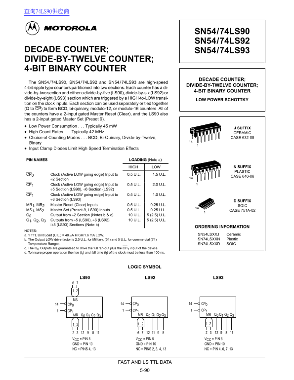
Page 1 Text Content
查询74LS90供应商
SN54/74LS90 SN54/74LS92
DECADE COUNTER; SN54/74LS93 DIVIDE-BY-TWELVE COUNTER; 4-BIT BINARY COUNTER
DECADE COUNTER;
The SN54/74LS90, SN54/74LS92 and SN54/74LS93 are high-speed
DIVIDE-BY-TWELVE COUNTER;
4-bit ripple type counters partitioned into two sections. Each counter has a di-
4-BIT BINARY COUNTER
vide-by-two section and either a divide-by-five (LS90), divide-by-six (LS92) or divide-by-eight (LS93) section which are triggered by a HIGH-to-LOW transi-
LOW POWER SCHOTTKY
tion on the clock inputs. Each section can be used separately or tied together (Q to CP) to form BCD, bi-quinary, modulo-12, or modulo-16 counters. All of the counters have a 2-input gated Master Reset (Clear), and the LS90 also has a 2-input gated Master Set (Preset 9). Low Power Consumption Typically 45 m W
J SUFFIX
High Count Rates Typically 42 MHz CERAMIC
Choice of Counting Modes BCD, Bi-Quinary, Divide-by-Twelve, CASE 632-08
Binary Input Clamp Diodes Limit High Speed Termination Effects
PIN NAMES LOADING (Note a)
HIGH LOW N SUFFIX PLASTIC
CP0 Clock (Active LOW going edge) Input to 0.5 U.L. 1.5 U.L.
CASE 646-06
÷2 Section
CP1 Clock (Active LOW going edge) Input to 0.5 U.L. 2.0 U.L.
÷5 Section (LS90), ÷6 Section (LS92)
CP1 Clock (Active LOW going edge) Input to 0.5 U.L. 1.0 U.L.
÷8 Section (LS93)
D SUFFIX
MR1, MR2 Master Reset (Clear) Inputs 0.5 U.L. 0.25 U.L. SOIC MS1, MS2 Master Set (Preset-9, LS90) Inputs 0.5 U.L. 0.25 U.L. CASE 751A-02 Q0 Output from ÷2 Section (Notes b & c) 10 U.L. 5 (2.5) U.L. Q1, Q2, Q3 Outputs from ÷5 (LS90), ÷6 (LS92), 10 U.L. 5 (2.5) U.L.
÷8 (LS93) Sections (Note b)
ORDERING INFORMATION
NOTES:
a. 1 TTL Unit Load (U.L.) = 40 µA HIGH/1.6 m A LOW. SN54LSXXJ Ceramic b. The Output LOW drive factor is 2.5 U.L. for Military, (54) and 5 U.L. for commercial (74) SN74LSXXN Plastic
b. Temperature Ranges. SN74LSXXD SOIC c. The Q0 Outputs are guaranteed to drive the full fan-out plus the CP1 input of the device. d. To insure proper operation the rise (tr) and fall time (tf) of the clock must be less than 100 ns.
LOGIC SYMBOL
LS90 LS92 LS93
CP0 CP0 CP0
CP1 CP1 CP1 MR Q0 Q1 Q2 Q3 MR Q0 Q1 Q2 Q3 MR Q0 Q1 Q2 Q3
VCC = PIN 5 VCC = PIN 5 VCC = PIN 5 GND = PIN 10 GND = PIN 10 GND = PIN 10 NC = PINS 4, 13 NC = PINS 2, 3, 4, 13 NC = PIN 4, 6, 7, 13
FAST AND LS TTL DATA
Page Summary Contents For MOTOROLA SN54 74LS90 SN54 74LS92 SN54 74LS93 DECADE COUNTER; DIVIDE- BY-TWELVE COUNTER; 4-BIT BINARY COUNTER User Manual and Data Sheet
Manual Details
| Brand | Motorola |
|---|---|
| Pages | 6 |
| File Size | 111.67 KB |
| Published | May 29, 2026 |
Enter the captcha to get the download link:

Frequently Asked Questions
What are the basic types of counting modes available?
The device can form BCD, bi-quinary, modulo-12, or modulo-16 counters by connecting its sections.
How is the unit load defined for current measurements?
One TTL Unit Load (U.L.) equals 40 μA high and 1.6 mA low.
What clock change triggers state changes in the counter?
State changes occur upon a HIGH-to-LOW transition on the clock input (CP).
Does powering down affect consumption?
The device is noted for its Low Power Consumption, typically drawing 45 mW.