# A B C D E F G H I J K L M N O P Q R S T U V W X Y Z

AD5258 Analog Devices User Guide and Specifications Manual

Summary

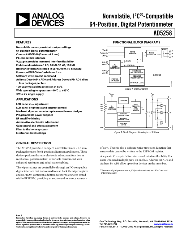
The AD5258 is a highly compact and reliable nonvolatile Digital Potentiometer designed to electronically replace mechanical resistors. Featuring an I²C-compatible interface and integrated EEPROM for data retention (maintaining settings even when powered off), it offers high precision and flexibility for multiple applications on a single bus. This manual provides comprehensive details on its operation, including read/write modes, functional block diagrams, technical specifications, and ideal use cases in automotive controls, LCD brightness adjustment, and complex electronics level setting.
📄 Preview 📖 Table of Contents Contents PAGE OF 24

Page 1 Text Content

Nonvolatile, I2C®-Compatible 64-Position, Digital Potentiometer

AD5258 FEATURES FUNCTIONAL BLOCK DIAGRAMS Nonvolatile memory maintains wiper settings

VDD RDAC

64-position digital potentiometer

VLOGIC RDAC

EEPROM

Compact MSOP-10 (3 mm × 4.9 mm) REGISTER

I2C-compatible interface

VLOGIC pin provides increased interface flexibility SCL

SDA I2C

End-to-end resistance 1 kΩ, 10 kΩ, 50 kΩ, 100 kΩ CONTROL

SERIAL INTERFACE

Resistance tolerance stored in EEPROM (0.1% accuracy)

AD0 COMMAND

Power-on EEPROM refresh time <1 ms AD1 DECODE LOGIC

AD5258

Software write protect command ADDRESS DECODE LOGIC

POWER-

Address Decode Pin AD0 and Address Decode Pin AD1 allow

ON RESET

CONTROL LOGIC

four packages per bus 100-year typical data retention at 55°C

Figure 1. Block Diagram

Wide operating temperature −40°C to +85°C

3 V to 5 V single supply VLOGIC VDD

APPLICATIONS

EEPROM

LCD panel VCOM adjustment SCL RDAC

SDA I2C REGISTER LCD panel brightness and contrast control SERIAL AND

AD0 INTERFACE LEVEL

AD1 SHIFTER

Mechanical potentiometer replacement in new designs

COMMAND Programmable power supplies DECODE LOGIC RF amplifier biasing ADDRESS DECODE LOGIC

Automotive electronics adjustment

CONTROL LOGIC

Gain control and offset adjustment

Fiber to the home systems

Figure 2. Block Diagram Showing Level Shifters

Electronics level settings

GENERAL DESCRIPTION

The AD5258 provides a compact, nonvolatile 3 mm × 4.9 mm of 0.1%. There is also a software write protection function that packaged solution for 64-position adjustment applications. These ensures data cannot be written to the EEPROM register.

devices perform the same electronic adjustment function as

A separate VLOGIC pin delivers increased interface flexibility. For

mechanical potentiometers1 or variable resistors, but with

users who need multiple parts on one bus, Address Bit AD0 and

enhanced resolution and solid-state reliability.

Address Bit AD1 allow up to four devices on the same bus.

The wiper settings are controllable through an I2C-compatible

1 The terms digital potentiometer, VR (variable resistor), and RDAC are used

digital interface that is also used to read back the wiper register 9-

interchangeably.

and EEPROM content in addition, resistor tolerance is stored within EEPROM, providing an end-to-end tolerance accuracy

Rev. B Information furnished by Analog Devices is believed to be accurate and reliable. However, no responsibility is assumed by Analog Devices for its use, nor for any infringements of patents or other

One Technology Way, P.O. Box 9106, Norwood, MA 02062-9106, U.S.A.

rights of third parties that may result from its use. Specifications subject to change without notice. No

license is granted by implication or otherwise under any patent or patent rights of Analog Devices. Tel: 781.329.4700 www.analog.com Trademarks and registered trademarks are the property of their respective owners. Fax: 781.461.3113 ©2005–2010 Analog Devices, Inc. All rights reserved.

Page Summary Contents For AD5258 Analog Devices User Guide and Specifications Manual

Page 1 Nonvolatile, I2C®-Compatible 64-Position, Digital Potentiometer AD5258 FEATURES FUNCTIONAL BLOCK DIAGRAMS Nonvolatile memory maintains wiper settings VDD RDAC 64-position digital potentiometer VLOGIC ...
Page 2 AD5258 TABLE OF CONTENTS Features .............................................................................................. 1 Storing/Restoring ......................................................
Page 3 AD5258 SPECIFICATIONS ELECTRICAL CHARACTERISTICS VDD = VLOGIC = 5 V ± 10%, or 3 V ± 10%; VA = VDD; VB = 0 V; −40°C &lt; TA &lt; +85°C, unless otherwise noted. Table 1. Parameter Symbol Conditions Min ...
Page 4 AD5258 Parameter Symbol Conditions Min Typ1 Max Unit POWER SUPPLIES Power Supply Range VDD 2.7 5.5 V Positive Supply Current IDD 0.5 2 μA Logic Supply VLOGIC 2.7 5.5 V Logic Supply Current ILOGIC VIH ...
Page 5 AD5258 TIMING CHARACTERISTICS VDD = VLOGIC = 5 V ± 10%, or 3 V ± 10%; VA = VDD; VB = 0 V; −40°C &lt; TA &lt; +85°C, unless otherwise noted. Table 2. Parameter Symbol Conditions Min Typ Max Unit I2C IN...
Page 6 AD5258 ABSOLUTE MAXIMUM RATINGS TA = 25°C, unless otherwise noted. Table 3. Stresses above those listed under Absolute Maximum Ratings Parameter Rating may cause permanent damage to the device. This i...
Page 7 AD5258 PIN CONFIGURATION AND FUNCTION DESCRIPTIONS AD5258 AD1 TOP VIEW VDD (Not to Scale) SDA GND SCL VLOGIC Figure 4. Pin Configuration Table 4. Pin Function Descriptions Pin No. Mnemonic Description...
Page 8 AD5258 PO TE TI ET ER IN (L SB EO ST AT NL (L SB EO ST AT IN (L SB TYPICAL PERFORMANCE CHARACTERISTICS VDD = VLOGIC = 5.5 V, RAB = 10 kΩ, TA = 25°C, unless otherwise noted. 0.5 0.10 0.4 0.08 0.3 0.06 ...
Page 9 AD5258 FS (L SB EO ST AT (L SB EO ST AT IN (L SB ZSE @ VDD = 2.7V ZSE @ VDD = 5.5V TEMPERATURE (°C) CODE (Decimal) Figure 14. Zero-Scale Error vs. Temperature Figure 11. R-INL vs. Code vs. Temperature...
Page 10 AD5258 x0 PO TE TI ET ER TE PC (p pm /° EO ST AT TE PC (p pm /° 100k RT @ VDD = 5.5V 50k RT @ VDD = 5.5V –50 10k RT @ VDD = 5.5V 100k 1k RT @ VDD = 5.5V CODE (Decimal) TEMPERATURE (°C) Figure 17. Rheo...
Page 11 AD5258 IN (d 10k IN (d VDD = VLOGIC = 5V –36 VDD = VLOGIC = 3V FREQUENCY (Hz) VIH (V) Figure 23. Gain vs. Frequency vs. Code, RAB = 50 kΩ Figure 25. Logic Supply Current vs. Input Voltage 9- CODE = MI...
Page 12 AD5258 0m V/ IV 5V /D IV 0m V/ IV 400ns/DIV 200ns/DIV Figure 27. Digital Feedthrough 9- Figure 29. Large-Signal Settling Time 9- 5V /D IV 2V /D IV 1µs/DIV Figure 28. Midscale Glitch, Code 0×7F to Code...
Page 13 AD5258 TEST CIRCUITS Figure 30 through Figure 35 illustrate the test circuits that define the test conditions used in the product specification tables. DUT V+ = VDD V+ = VDD ± 10% 1LSB = V+/2N ΔVMS% P...
Page 14 AD5258 THEORY OF OPERATION The AD5258 is a 64-position digitally controlled variable Similar to the mechanical potentiometer, the resistance of the resistor (VR) device. The wipers default value prior...
Page 15 AD5258 I2C INTERFACE Note that the wiper’s default value prior to programming the READING EEPROM is midscale. Assuming the register of interest was not just written to, it is The master initiates a da...
Page 16 AD5258 I2C BYTE FORMATS The following generic, write, read, and store/restore control Table 5. Device Address Lookup registers for the AD5258 refer to the device addresses listed in AD1 Address Pin AD...
Page 17 AD5258 READ MODES Read modes are referred to as traditional because the first two interested in reading a register that was previously written to. bytes for all three cases are dummy bytes that functi...
Page 18 AD5258 TOLERANCE READBACK MODES Table 15. Traditional Readback of Tolerance (Individually) 7-Bit Device Address 7-Bit Device Address (See Table 5) 0 SA 0 0 1 1 1 1 1 0 SA (See Table 5) 1 SA D7 D6 D5 D...
Page 19 AD5258 ESD PROTECTION OF DIGITAL PINS AND Similarly, it is also good practice to bypass the power supplies RESISTOR TERMINALS with quality capacitors for optimum stability. Supply leads to the device ...
Page 20 AD5258 DISPLAY APPLICATIONS CIRCUITRY affect that node’s bias because it is only on the order of microamps. VLOGIC is tied to the microcontroller’s (MCU) 3.3 V A special feature of the AD5258 is its u...
Page 21 AD5258 OUTLINE DIMENSIONS PIN IDENTIFIER 0.50 BSC 15° MAX0.95 0.85 1.10 MAX 0.75 COPLANARITY 0.10 COMPLIANT TO JEDEC STANDARDS MO-187-BA Figure 46. 10-Lead Mini Small Outline Package [MSOP] (RM-10) Di...
Page 22 AD5258 NOTES Rev. B | Page 22 of 24
Page 23 AD5258 NOTES Rev. B | Page 23 of 24
Page 24 AD5258 NOTES Purchase of licensed I2C components of Analog Devices or one of its sublicensed Associated Companies conveys a license for the purchaser under the Philips I2C Patent Rights to use these c...

Manual Details

Brand Analog Devices
Pages 24
File Size 597.40 KB
Published June 16, 2026
4 views

Enter the captcha to get the download link:

captcha

Frequently Asked Questions

What is the operating temperature range for the AD5258?

The device is rated for a wide operating temperature range from -40°C to +85°C.

How can multiple devices be connected on one bus?

Address Bits AD0 and AD1 allow up to four devices to be located on the same I²C bus.

Does the device protect against data loss in EEPROM?

It has a software write protection command that prevents data from being written to the EEPROM register, ensuring retention.

What is the function of the V pin?

A separate V pin delivers increased interface flexibility by allowing operation up to 4.8V (based on selected resistors).

What type of adjustment applications can this device support?

It supports various applications such as LCD panel brightness/contrast control, RF amplifier biasing, and gain/offset adjustments.