AD5172 AD5173 256-Position One-Time Programmable Dual-Channel I 2 C Digital Potentiometers Data Sheet Owner's Manual
Summary
The AD5172/AD5173 are high-resolution, dual-channel One-Time Programmable (OTP) digital potentiometers designed as a reliable, cost-effective replacement for mechanical trimmers and EEMEM. Featuring a unique temporary overwrite capability, they allow engineers to cycle through adjustments multiple times before permanent factory setting. This manual details the device's electrical characteristics, layout guidelines, and uses specialized software instructions for initial programming. Ideal for industrial, automotive, and calibration systems requiring precise sensor adjustment or electronics level setting across wide temperature ranges.
Page 1 Text Content
查询AD5172供应商
256-Position One-Time Programmable Dual-Channel I2C Digital Potentiometers
AD5172/AD5173
FEATURES FUNCTIONAL BLOCK DIAGRAMS 2-channel, 256-position A1 W1 B1 A2 W2 B2
OTP (one-time programmable) set-and-forget resistance setting, low cost alternative to EEMEM Unlimited adjustments prior to OTP activation OTP overwrite allows dynamic adjustments with user
VDD FUSE
defined preset
LINKS
End-to-end resistance: 2.5 kΩ, 10 kΩ, 50 kΩ, 100 kΩ
Compact MSOP-10 (3 mm × 4.9 mm) package RDAC RDAC
REGISTER 1 REGISTER 2
Fast settling time: t S = 5 µs typ in power-up Full read/write of wiper register Power-on preset to midscale Extra package address decode pins AD0 and AD1 (AD5173) SDA
SERIAL INPUT Single supply 2.7 V to 5.5 V SCL REGISTER
Low temperature coefficient: 35 ppm/°C
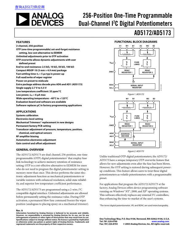
Figure 1. AD5172
Low power, IDD = 6 µA max Wide operating temperature: –40°C to +125°C W1 B1 W2 B2 Evaluation board and software are available Software replaces µC in factory programming applications
APPLICATIONS Systems calibration FUSE
LINKS
Electronics level setting Mechanical Trimmers® replacement in new designs
RDAC RDAC
Permanent factory PCB setting REGISTER 1 REGISTER 2
Transducer adjustment of pressure, temperature, position, chemical, and optical sensors AD0
ADDRESS AD1 DECODE
RF amplifier biasing Automotive electronics adjustment
SERIAL INPUT
Gain control and offset adjustment
SCL REGISTER
GENERAL OVERVIEW
Figure 2. AD5173
The AD5172/AD5173 are dual channel, 256-position, one-time
Unlike traditional OTP digital potentiometers, the AD5172/
programmable (OTP) digital potentiometers1 that employ fuse
3- 0- AD5173 have a unique temporary OTP overwrite feature that 3- 0-
link technology to achieve memory retention of resistance
allows for new adjustments even after the fuse has been blown.
setting. OTP is a cost-effective alternative to EEMEM for users
However, the OTP setting is restored during subsequent power-
who do not need to program the digital potentiometer setting in
up conditions. This feature allows users to treat these digital
memory more than once. This device performs the same elec-
potentiometers as volatile potentiometers with a programmable
tronic adjustment function as mechanical potentiometers or
preset.
variable resistors with enhanced resolution, solid-state reliabil- ity, and superior low temperature coefficient performance. For applications that program the AD5172/AD5173 at the
factory, Analog Devices offers device programming software
The AD5172/AD5173 are programmed using a 2-wire, I2C
running on Windows® NT®, 2000, and XP® operating systems.
compatible digital interface. Unlimited adjustments are allowed
This software effectively replaces any external I2C controllers,
before permanently setting the resistance value. During OTP
thus enhancing the time-to-market of the user’s systems.
activation, a permanent blow fuse command freezes the wiper position (analogous to placing epoxy on a mechanical trimmer). 1The terms digital potentiometer, VR, and RDAC are used interchangeably.
Rev. A Information furnished by Analog Devices is believed to be accurate and reliable. However, no responsibility is assumed by Analog Devices for its use, nor for any infringements of patents or other rights of third parties that may result from its use.
One Technology Way, P.O. Box 9106, Norwood, MA 02062-9106, U.S.A.
Specifications subject to change without notice. No license is granted by implication
or otherwise under any patent or patent rights of Analog Devices. Trademarks and Tel: 781.329.4700 www.analog.com registered trademarks are the property of their respective owners. Fax: 781.326.8703 © 2003 Analog Devices, Inc. All rights reserved.
Page Summary Contents For AD5172 AD5173 256-Position One-Time Programmable Dual-Channel I 2 C Digital Potentiometers Data Sheet Owner's Manual
Manual Details
| Brand | Dual |
|---|---|
| Pages | 24 |
| File Size | 739.84 KB |
| Published | June 03, 2026 |
Enter the captcha to get the download link:

Frequently Asked Questions
What is the operating temperature range for this device?
It supports a wide operating temperature from –40°C to +125°C.
Is the AD5173 permanently set after initial programming?
The OTP setting that occurs during activation freezes the wiper position, similar to placing epoxy on a mechanical trimmer.
How are these digital potentiometers programmed for factory use?
Analog Devices provides device programming software that is compatible with a 2-wire, I²C digital interface and runs on Windows® NT®, 2000, and XP® operating systems.