Vishay Surface Mount AutomotiveTransient Voltage SuppressorsHigh Temperature Stability & High ReliabilityConditions Data Sheet Owner's Manual
Summary
This technical manual provides comprehensive specifications for the TPSMA series of Transient Voltage Suppressors (TVS). These high-reliability components are engineered to protect sensitive electronic circuits from dangerous transient voltage surges, such as those caused by inductive load switching or line fluctuations. Ideal for system designers in industrial, automotive, computer, and telecommunication fields, this guide details electrical performance, mechanical ratings, and application guidelines necessary for implementing robust surge suppression solutions.
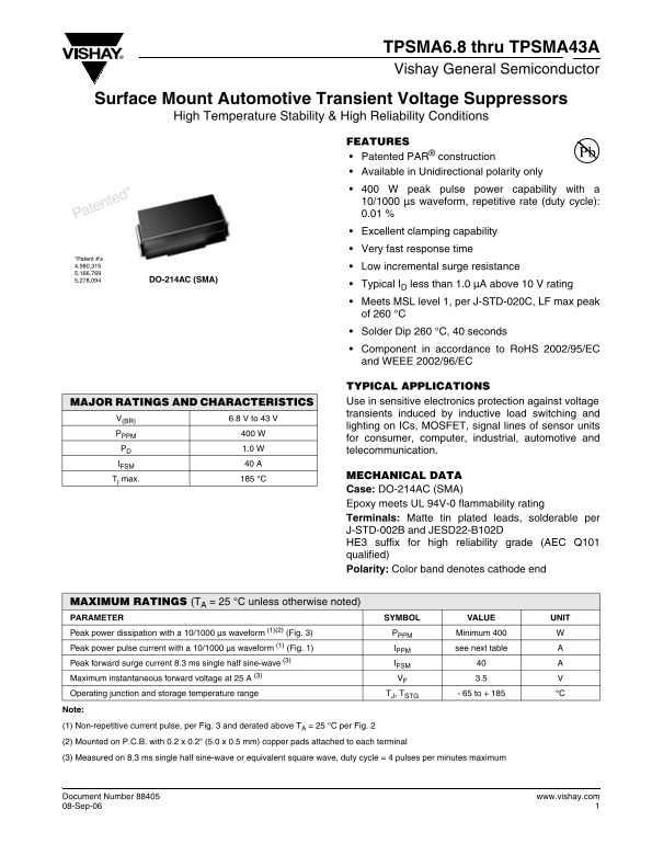
Page 1 Text Content
TPSMA6.8 thru TPSMA43A Vishay General Semiconductor
Surface Mount Automotive Transient Voltage Suppressors
High Temperature Stability & High Reliability Conditions
FEATURES Patented PAR® construction Available in Unidirectional polarity only 400 W peak pulse power capability with a 10/1000 µs waveform, repetitive rate (duty cycle): Patented* 0.01 % Excellent clamping capability Very fast response time
*Patent #'s 4,980,315 Low incremental surge resistance 5,166,769 5,278,094 DO-214AC (SMA)
Typical ID less than 1.0 µA above 10 V rating Meets MSL level 1, per J-STD-020C, LF max peak of 260 °C Solder Dip 260 °C, 40 seconds Component in accordance to Ro HS 2002/95/EC and WEEE 2002/96/EC
TYPICAL APPLICATIONS MAJOR RATINGS AND CHARACTERISTICS Use in sensitive electronics protection against voltage transients induced by inductive load switching and
V(BR) 6.8 V to 43 V
lighting on ICs, MOSFET, signal lines of sensor units
PPPM 400 W
for consumer, computer, industrial, automotive and
PD 1.0 W telecommunication. IFSM 40 A
MECHANICAL DATA
Tj max. 185 °C
Case: DO-214AC (SMA) Epoxy meets UL 94V-0 flammability rating Terminals: Matte tin plated leads, solderable per J-STD-002B and JESD22-B102D HE3 suffix for high reliability grade (AEC Q101 qualified) Polarity: Color band denotes cathode end
MAXIMUM RATINGS (TA = 25 °C unless otherwise noted) PARAMETER SYMBOL VALUE UNIT Peak power dissipation with a 10/1000 µs waveform (1)(2) (Fig. 3) PPPM Minimum 400 W Peak power pulse current with a 10/1000 µs waveform (1) (Fig. 1) IPPM see next table A Peak forward surge current 8.3 ms single half sine-wave (3) IFSM 40 Maximum instantaneous forward voltage at 25 A (3) VF 3.5 Operating junction and storage temperature range TJ, TSTG - 65 to + 185 °C
Note:
(1) Non-repetitive current pulse, per Fig. 3 and derated above TA = 25 °C per Fig. 2
(2) Mounted on P.C.B. with 0.2 x 0.2" (5.0 x 0.5 mm) copper pads attached to each terminal
(3) Measured on 8.3 ms single half sine-wave or equivalent square wave, duty cycle = 4 pulses per minutes maximum
Document Number 88405 www.vishay.com 08-Sep-06
Page Summary Contents For Vishay Surface Mount AutomotiveTransient Voltage SuppressorsHigh Temperature Stability & High ReliabilityConditions Data Sheet Owner's Manual
Manual Details
| Brand | Vishay |
|---|---|
| Pages | 5 |
| File Size | 89.08 KB |
| Published | June 02, 2026 |
Enter the captcha to get the download link:

Frequently Asked Questions
What is the suitable mounting procedure for this component?
The terminals are matte tin plated leads, solderable per J-STD-002B and JESD22-B102D.
What types of electronics benefit from using these voltage suppressors?
They protect sensitive electronics against transients from inductive load switching, V 6.8V to 43V lighting, ICs, MOSFETs, and sensor signal lines.
Is this device suitable for bidirectional voltage protection?
No, the units are available in Unidirectional polarity only.
What is the specified operational temperature range?
The operating junction and storage temperature range (T/STG) is -65 to +185 °C.