Vishay SFH618A 628A Data Sheet Manual
Summary
These optocouplers are essential components for reliable electrical signaling, providing high-isolation coupling between physically separated circuits. Featuring a GaAs infrared emitter and a phototransistor detector, the SFH series is optimized for robust signal transfer in demanding environments. This manual serves as a comprehensive technical resource, detailing maximum ratings, Coupling Transfer Ratios (CTR), thermal characteristics, and performance curves. Ideal for engineers designing industrial controls, battery-powered electronics, or telecom systems requiring stable, high-integrity electrical isolation.
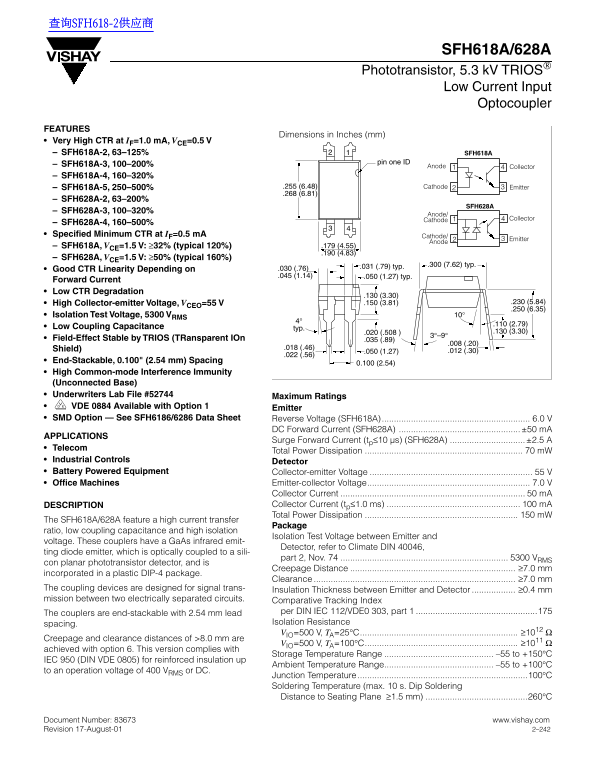
Page 1 Text Content
查询SFH618-2供应商
SFH618A/628A
Phototransistor, 5.3 k V TRIOS
Low Current Input Optocoupler
FEATURES
Dimensions in Inches (mm)
Very High CTR at =1.0 m A, =0.5 V
– SFH618A-2, 63–125% SFH618A
pin one ID
– SFH618A-3, 100–200% Anode
Collector
– SFH618A-4, 160–320%
– SFH618A-5, 250–500% .255 (6.48) Cathode Emitter .268 (6.81)
– SFH628A-2, 63–200%
SFH628A
– SFH628A-3, 100–320%
Anode/
Cathode Collector
– SFH628A-4, 160–500% Specified Minimum CTR at =0.5 m A Cathode/
Emitter
Anode
– SFH618A, =1.5 V: 32% (typical 120%) .179 (4.55)
– SFH628A, =1.5 V: 50% (typical 160%)
.031 (.79) typ. .300 (7.62) typ.
Good CTR Linearity Depending on .030 (.76) .045 (1.14) .050 (1.27) typ.
Forward Current Low CTR Degradation
High Collector-emitter Voltage, =55 V .150 (3.81) .230 (5.84)
Isolation Test Voltage, 5300 V 10°
Low Coupling Capacitance typ.
Field-Effect Stable by TRIOS (TRansparent IOn .035 (.89)
Shield) .018 (.46)
End-Stackable, 0.100" (2.54 mm) Spacing
High Common-mode Interference Immunity (Unconnected Base) Underwriters Lab File #52744 Maximum Ratings VDE 0884 Available with Option 1 Emitter SMD Option — See SFH6186/6286 Data Sheet Reverse Voltage (SFH618A)............................................................. 6.0 V
DC Forward Current (SFH628A) ..................................................±50 m A
APPLICATIONS
Surge Forward Current (t 10 µs) (SFH628A) ...............................±2.5 A
Telecom
Total Power Dissipation 70 m W
Industrial Controls Detector Battery Powered Equipment Collector-emitter Voltage 55 V Office Machines Emitter-collector Voltage................................................................... 7.0 V
Collector Current 50 m A DESCRIPTION Collector Current (t 1.0 ms) 100 m A Total Power Dissipation 150 m W
The SFH618A/628A feature a high current transfer
Package
ratio, low coupling capacitance and high isolation
Isolation Test Voltage between Emitter and
voltage. These couplers have a Ga As infrared emit-
Detector, refer to Climate DIN 40046,
ting diode emitter, which is optically coupled to a sili-
part 2, Nov. 74 5300 V
con planar phototransistor detector, and is
Creepage Distance 7.0 mm
incorporated in a plastic DIP-4 package.
Clearance 7.0 mm
The coupling devices are designed for signal trans- Insulation Thickness between Emitter and Detector 0.4 mm mission between two electrically separated circuits. Comparative Tracking Index
The couplers are end-stackable with 2.54 mm lead per DIN IEC 112/VDE0 303, part 1 ..................................................175 spacing. Isolation Resistance =500 V, =25 C................................................................. IO
Creepage and clearance distances of >8.0 mm are
=500 V, =100 C............................................................... IO
achieved with option 6. This version complies with
Storage Temperature Range –55 to +150
IEC 950 (DIN VDE 0805) for reinforced insulation up
Ambient Temperature Range............................................. –55 to +100
to an operation voltage of 400 V or DC.
Junction Temperature ......................................................................100 Soldering Temperature (max. 10 s. Dip Soldering Distance to Seating Plane 1.5 mm) ..........................................260
Document Number: 83673 www.vishay.com Revision 17-August-01 2–242
Page Summary Contents For Vishay SFH618A 628A Data Sheet Manual
Manual Details
| Brand | Vishay |
|---|---|
| Pages | 4 |
| File Size | 439.10 KB |
| Published | June 02, 2026 |
Enter the captcha to get the download link:

Frequently Asked Questions
What is the acceptable operating temperature range for this component?
The ambient temperature range is –55 to +100°C, while the storage temperature range is –55 to +150°C.
How far apart must they be mounted if I stack multiple units?
The couplers are end-stackable with a minimum spacing of 2.54 mm lead spacing.
What is the high voltage isolation rating between leads?
The specified Isolation Test Voltage is 5300 V RMS.