Vishay - K817P, K827PH, K847PH Data Handbook Specifications User Manual
Summary
These high-reliability phototransistor optocouplers provide superior electrical isolation for demanding control systems. Featuring up to 5000V isolation voltage and a wide operational temperature range, they are available in single, dual, or quad channel packages. This detailed guide covers every aspect needed for professional integration, presenting absolute maximum ratings, multiple Current Transfer Ratio (CTR) groupings, and comprehensive switching characteristics. Essential for engineers designing PLCs, modems, and industrial automation equipment needing guaranteed isolation and performance.
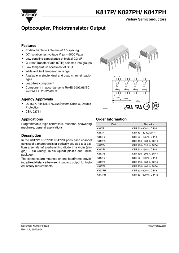
Page 1 Text Content
K817P/ K827PH/ K847PH
Vishay Semiconductors
Optocoupler, Phototransistor Output
Features Endstackable to 2.54 mm (0.1") spacing DC isolation test voltage VISO = 5000 VRMS Low coupling capacitance of typical 0.3 p F Current Transfer Ratio (CTR) selected into groups Low temperature coefficient of CTR Wide ambient temperature range Available in single, dual and quad channel pack- ages Lead-free component Component in accordance to Ro HS 2002/95/EC and WEEE 2002/96/EC
Agency Approvals
UL1577, File No. E76222 System Code U, Double
e3 Pb
Protection 17203_1
Pb-free
CSA 93751
Applications Order Information Programmable logic controllers, modems, answering Part Remarks machines, general applications
K817P CTR 50 - 600 %, DIP-4
K817P1 CTR 40 - 80 %, DIP-4
Description
K817P2 CTR 63 - 125 %, DIP-4
In the K817P/ K827PH/ K847PH parts each channel
K817P3 CTR 100 - 200 %, DIP-4
consist of a phototransistor optically coupled to a gal-
K817P4 CTR 160 - 320 %, DIP-4
lium arsenide infrared-emitting diode in a 4-pin (sin-
K817P5 CTR 50 - 150 %, DIP-4
gle); 8 pin (dual); 16-pin (quad) plastic dual inline
K817P6 CTR 100 - 300 %, DIP-4
package.
K817P7 CTR 80 - 160 %, DIP-4
The elements are mounted on one leadframe provid-
ing a fixed distance between input and output for high- K817P8 CTR 130 - 260 %, DIP-4
est safety requirements. K817P9 CTR 200 - 400 %, DIP-4
K827PH CTR 50 - 600 %, DIP-8 K847PH CTR 50 - 600 %, DIP-16
Document Number 83522 www.vishay.com Rev. 1.7, 26-Oct-04
Page Summary Contents For Vishay - K817P, K827PH, K847PH Data Handbook Specifications User Manual
Manual Details
| Brand | Vishay |
|---|---|
| Pages | 10 |
| File Size | 260.65 KB |
| Published | June 06, 2026 |
Enter the captcha to get the download link:

Frequently Asked Questions
What is the maximum AC isolation test voltage?
The device provides an AC isolation test voltage of up to 5000 V RMS.
What temperature range can this component operate in?
The operating ambient temperature range is specified as -40 to +100 °C.
Is this optocoupler suitable for life-sustaining applications?
No, the products are not designed for use in medical, life-saving, or life-sustaining applications.
What package options are available for various capacities?
It is available in single (DIP-4), dual (DIP-8), and quad (DIP-16) plastic packages.